
Hard rail type gantry numerical control milling machine

A CNC milling machine and hard rail technology, applied in the direction of large fixed members, metal processing machinery parts, metal processing equipment, etc., can solve problems such as weak stability, high maintenance costs, and damage to rolling line rails, so as to reduce machining accuracy The effect of large contact area of ​​the guide rail and the smooth operation of the machine tool

Pending Publication Date: 2018-03-09
JIANGMEN GAOCHENG NUMERICAL CONTROL MACHINERY
View PDF6 Cites 1 Cited by
  • Summary
  • Abstract
  • Description
  • Claims
  • Application Information

AI Technical Summary

Problems solved by technology

[0002] The existing gantry CNC milling machine has only one spindle to drive the tool to process. If it is necessary to add another spindle to work, it can only add another gantry and other related spindle installation devices, which will cause inconvenient processing, and in limited working space Under these conditions, it is unreasonable to add other processing devices, and it will increase the safety of the working environment and various related costs
If a double-drive design is adopted, that is, one screw rod is equipped with two spindles, processing can be performed at the same time to improve efficiency. However, the traditional mobile device adopts a rolling line rail structure, which has a small bearing capacity, weak stability, and insufficient rigidity. , if it is used to carry multiple spindles, it will easily lead to damage, bending and deformation of the rolling line rail, which will affect the machining accuracy of the milling machine and cause high maintenance costs

Method used


Image

  • Hard rail type gantry numerical control milling machine
  • Hard rail type gantry numerical control milling machine
  • Hard rail type gantry numerical control milling machine

Examples


Embodiment Construction

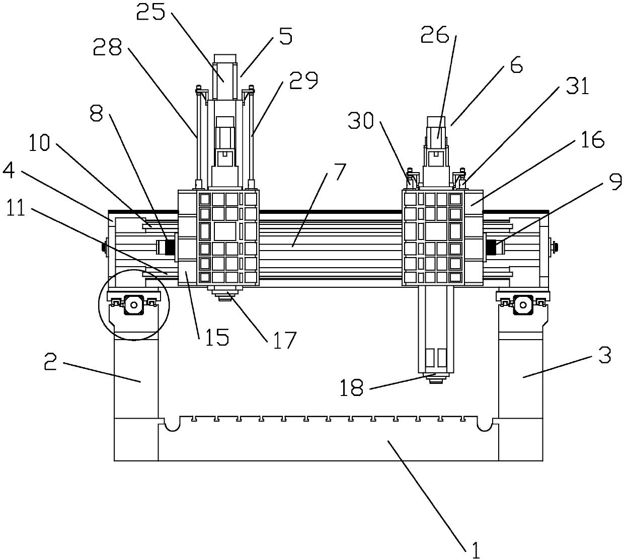
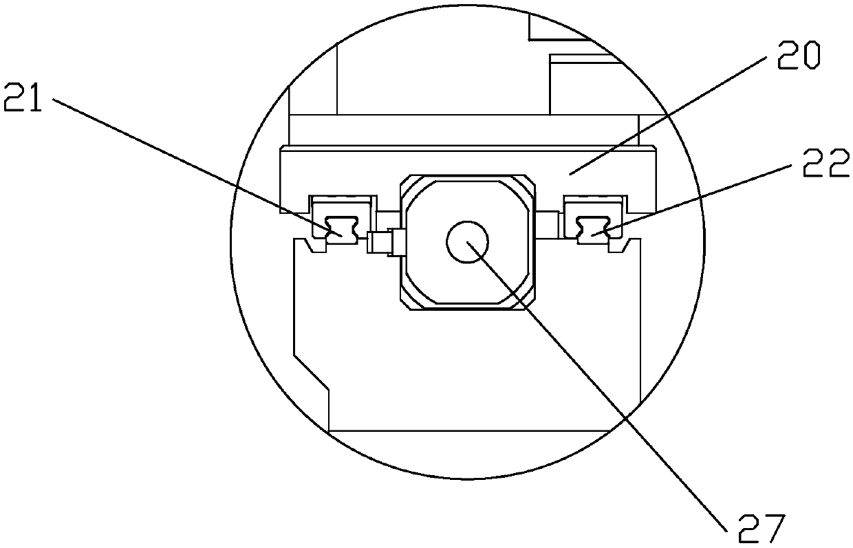
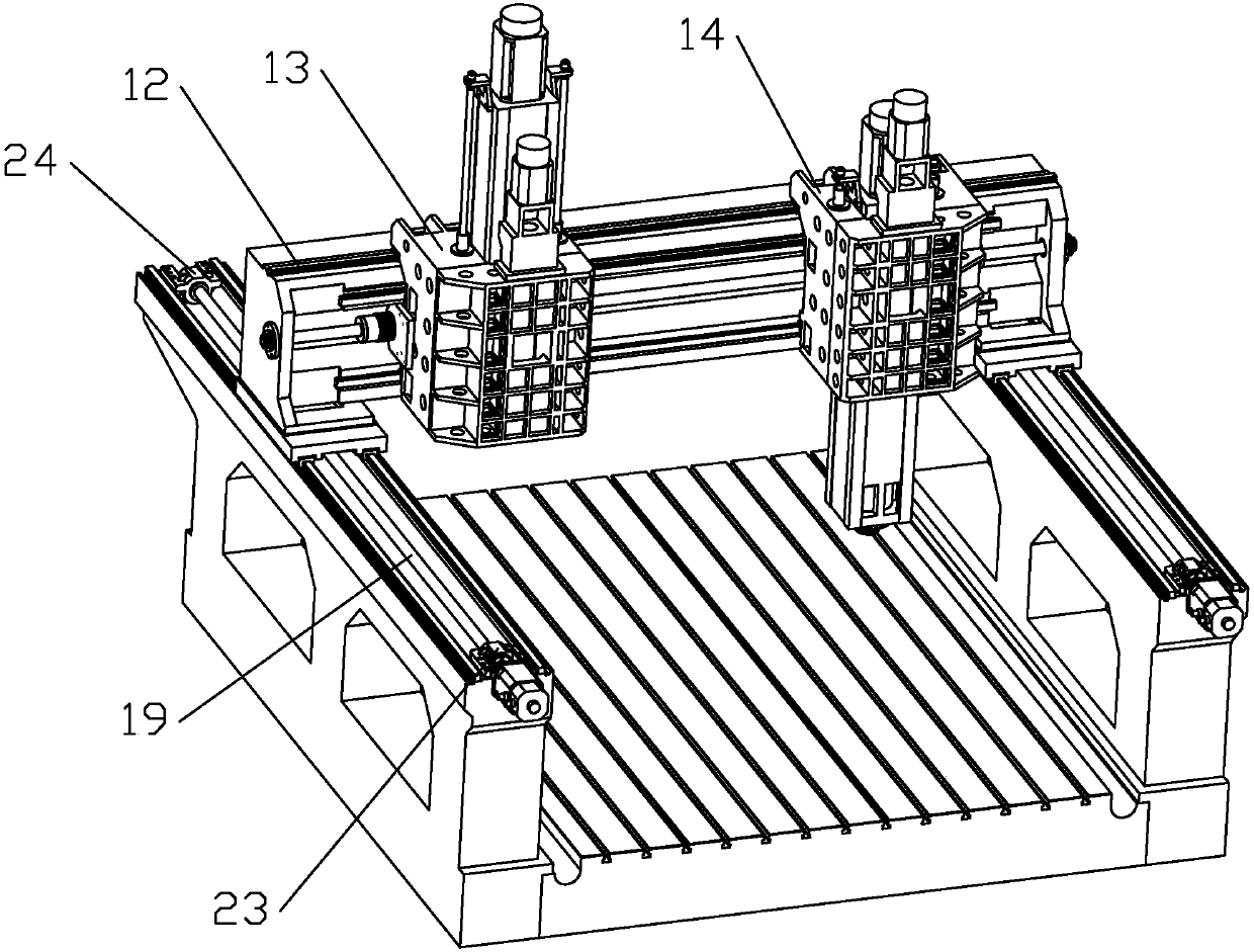
[0020] Such as Figure 1 to Figure 3 As shown, one of the embodiments provided by the present invention, a hard rail type gantry CNC milling machine, includes a workbench body 1, a gantry frame and a processing device, and the gantry frame includes left and right sides respectively fixed on the workbench body 1. The first pillar 2 and the second pillar 3 on the right side, and the crossbeam 4, the first pillar 2 and the second pillar 3 are respectively connected to the two ends of the crossbeam 4 through a synchronous movable device, and the processing device includes The first Z-axis device 5 and the second Z-axis device 6 on the beam 4, the beam 4 is provided with a first guide rail 10 and a second guide rail 11 fixed on the front end surface of the beam 4, and a first guide rail 11 fixed on the upper end surface of the beam. Three guide rails 12, the first guide rail 10, the second guide rail 11 and the third guide rail 12 are sliding hard rail tracks with an inverted V-sha...


PUM


Abstract

The invention discloses a hard rail type gantry numerical control milling machine, which comprises a workbench main body, a portal frame, and a processing device; the portal frame comprises a first supporting pillar and a second supporting pillar, and a cross beam; the first supporting pillar and the second supporting pillar are fixed at the left side and the right side of the workbench main body,and connected to both ends of the cross beam through a synchronous moving device; the processing device comprises a first Z-axis device and a second Z-axis device arranged on the cross beam; the cross beam is provided with a first lead rail, fixed at the front end face of the cross beam, a second lead rail, and a third lead rail on the upper end face of the cross beam; the first, second and thirdlead rails are gliding hard rails of which sections are in the shape of reversed V. The hard rail type gantry numerical control milling machine is simple and reliable in structure, and the gliding hard rail integrally casted with the machine tool is used as the moving lead rail, and can bear big load; the contact area of the lead rail is big, and the machine tool running is more stable; thus theinfluence of the vibration of the machine tool on the processing precision is reduced, and the maintenance cost is low.

Description

technical field [0001] The invention relates to the technical field of milling machine processing equipment, in particular to a hard rail type gantry numerical control milling machine. Background technique [0002] The existing gantry CNC milling machine has only one spindle to drive the tool to process. If it is necessary to add another spindle to work, it can only add another gantry and other related spindle installation devices, which will cause inconvenient processing, and in limited working space Under these conditions, it is unreasonable to add other processing devices, and it will increase the safety of the working environment and various related costs. If a double-drive design is adopted, that is, one screw rod is equipped with two spindles, processing can be performed at the same time to improve efficiency. However, the traditional mobile device adopts a rolling line rail structure, which has a small bearing capacity, weak stability, and insufficient rigidity. , if...

Claims


Application Information

Patent Timeline
Patent Type & Authority Applications(China)
IPC IPC(8): B23Q1/01
CPCB23Q1/012B23Q1/017
Inventor 邓文
Owner JIANGMEN GAOCHENG NUMERICAL CONTROL MACHINERY
Learn More