Eureka AIR delivers breakthrough ideas for toughest innovation challenges, trusted by R&D personnel around the world.

Shaft sleeve

A shaft sleeve and integrated technology, applied in the direction of shafts, bearings, bearing components, etc., can solve the problems of inconvenient installation and achieve the effect of convenient installation, simple structure and high strength

Inactive Publication Date: 2018-03-09
宁波市海曙古林新睦粉末冶金厂
View PDF0 Cites 0 Cited by
  • Summary
  • Abstract
  • Description
  • Claims
  • Application Information

AI Technical Summary

Problems solved by technology

[0004] The problem to be solved by the present invention is to provide a shaft sleeve to overcome the inconvenience of installation in the prior art

Method used


Image

  • Shaft sleeve

Examples


Embodiment Construction

[0012] The specific implementation manners of the present invention will be further described in detail below in conjunction with the accompanying drawings and embodiments. The following examples are used to illustrate the present invention, but are not intended to limit the scope of the present invention.

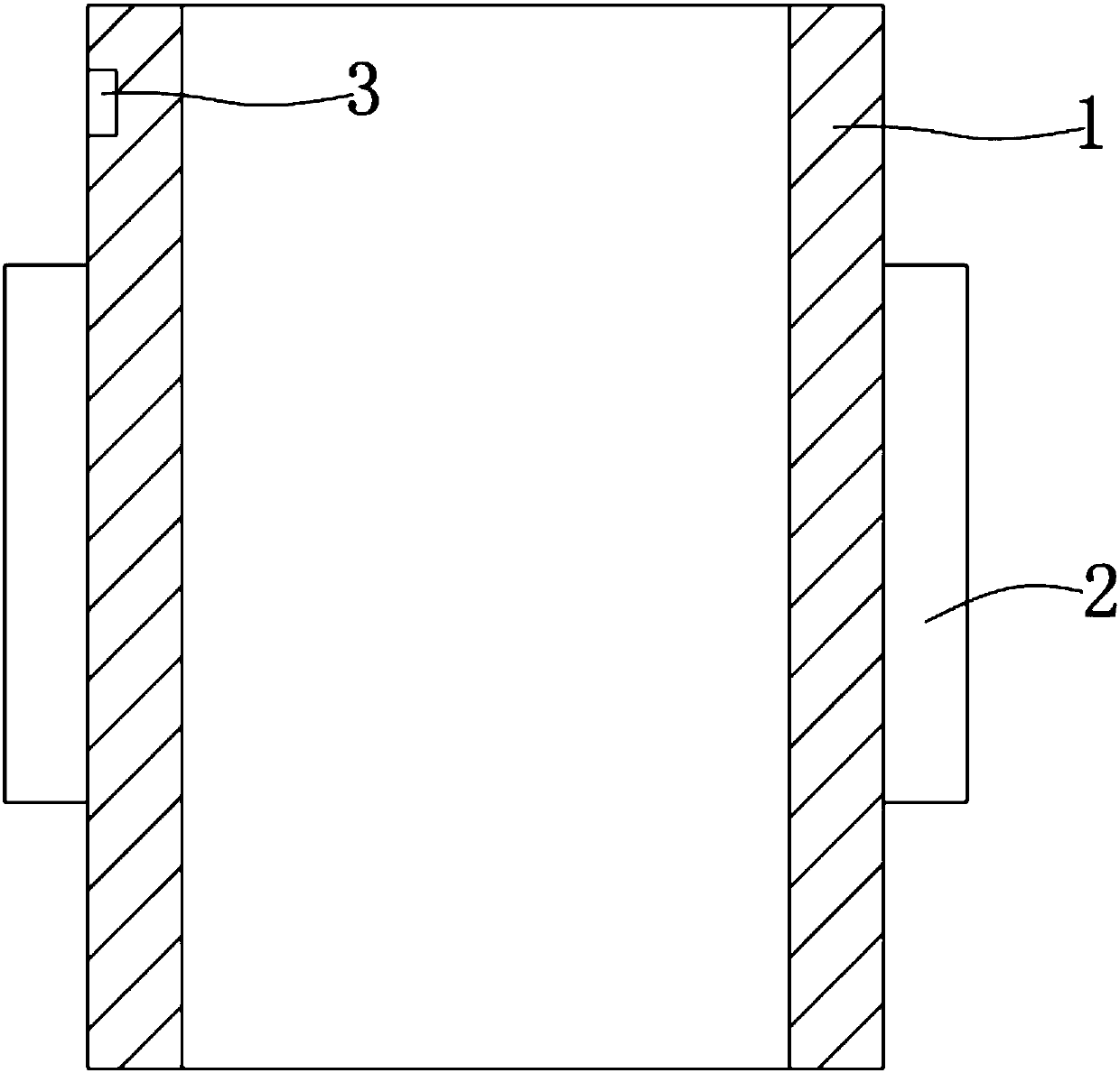
[0013] like figure 1 As shown, a bushing of the present invention includes a bushing body 1, the outer wall of the bushing body 1 is provided with a groove 2, and the groove 2 is integrally formed with the bushing body 1; the bushing body 1. The inner diameter is 25 mm; a groove 3 is also provided on one side of the outer wall of the main body 1 of the sleeve.

[0014] The sleeve main body 1 is made of iron alloy material. The length of the sleeve main body 1 is 65mm.

[0015] The shaft sleeve of the invention has simple structure, convenient installation and high strength.

[0016] In summary, the above-mentioned embodiments are not limiting embodiments of the present...


PUM

PropertyMeasurementUnit
The inside diameter ofaaaaaaaaaa
Body lengthaaaaaaaaaa

Abstract

The invention provides a shaft sleeve, which includes a shaft sleeve main body, the outer wall of the shaft sleeve main body is provided with a groove, and the groove is integrally formed with the shaft sleeve main body; the inner diameter of the shaft sleeve main body is 25mm; the shaft sleeve A groove is also provided on one side of the outer wall of the main body. The invention has simple structure, convenient installation and high strength.

Description

technical field [0001] The invention relates to a shaft sleeve. Background technique [0002] The shaft sleeve is a cylindrical mechanical part that is sleeved on the rotating shaft and is an integral part of the sliding bearing. Generally speaking, the shaft sleeve and the bearing seat adopt an interference fit, while the shaft sleeve adopts a clearance fit. Bushing is the sleeve on the propeller shaft or stern shaft. The bearing is a component that fixes and reduces the friction coefficient of the load during the mechanical transmission process. The existing shaft sleeve is inconvenient to install. Contents of the invention [0003] (1) Technical problems to be solved [0004] The problem to be solved by the present invention is to provide a shaft sleeve to overcome the disadvantage of inconvenient installation in the prior art. [0005] (2) Technical solution [0006] In order to solve the above technical problem, the present invention provides a bushing, includin...

Claims


Application Information

Patent Timeline
IPC IPC(8): F16C33/06
CPCF16C33/06F16C2204/60
Inventor 李惠峰
Owner 宁波市海曙古林新睦粉末冶金厂
Why Eureka
Eureka Blog
Learn More