Fluid flow system of flow cytometry and control method thereof

A flow cytometer and liquid flow technology, applied in the field of analytical instruments, can solve the problems of the influence of experimental accuracy, the control of the stability of the sheath fluid, and the influence of the focus width, etc., so as to facilitate cleaning and plugging , Eliminate the sheath fluid pulsation phenomenon, reduce the effect of volume

Pending Publication Date: 2018-03-09
成都索尔恩科技有限公司
View PDF4 Cites 11 Cited by
  • Summary
  • Abstract
  • Description
  • Claims
  • Application Information

AI Technical Summary

Problems solved by technology

However, the above-mentioned liquid flow system still does not realize the control of the stability of the sheath liquid, the feedback control of the

Method used


Image

  • Fluid flow system of flow cytometry and control method thereof
  • Fluid flow system of flow cytometry and control method thereof
  • Fluid flow system of flow cytometry and control method thereof

Examples


Embodiment 1

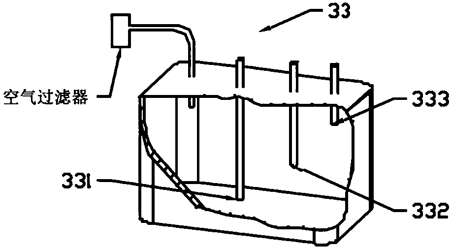
[0076] figure 1 It is a cross-sectional view of a single-chamber sheath buffer device. The sheath fluid buffer device 33 has at least one inlet and at least two outlets, wherein the inlet 333 communicates with the first sheath fluid circulation pump, the outlet 331 communicates with the flow chamber, and the outlet 332 communicates with the second sheath fluid circulation pump. The height of the outlet 331 is lower than that of the outlet 332 . The first sheath liquid circulation pump injects the sheath liquid into the buffer device, and when the liquid level is higher than the outlet 332, the excess sheath liquid is drawn out by the second sheath liquid circulation pump. The height difference between the outlet 332 and the outlet 331 determines the positional potential energy of the sheath fluid, and it remains constant. The sheath buffer is vented to atmosphere through an air filter.

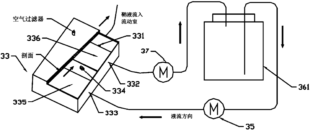
[0077] figure 2 It is the schematic diagram and working flow diagram of the position ...

Embodiment 2

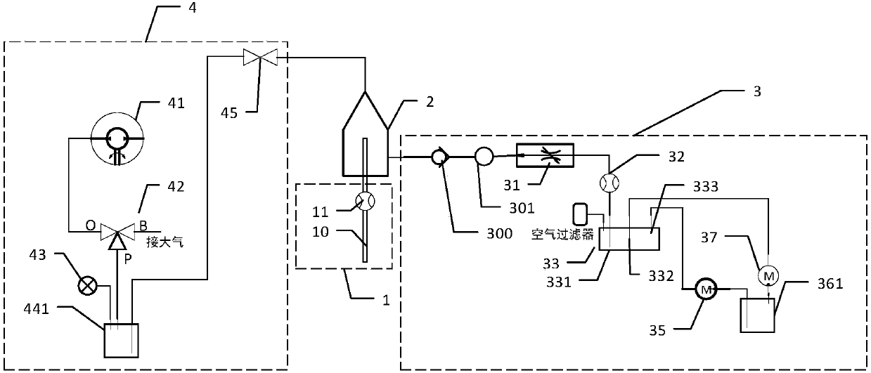
[0079] Such as image 3 As shown, a flow cytometer liquid flow system includes a sample liquid channel 1, a flow chamber 2, a sheath liquid channel 3 and a negative pressure source channel 4, and the sample liquid channel 1, the sheath liquid channel 3, and the negative pressure source The channels 4 are all connected to the flow chamber 2; the sample liquid channel 1 includes a liquid inlet sample needle 10 and a sample liquid flow sensor 11 arranged in sequence, and the sample liquid in the liquid inlet sample needle 11 passes through the sample liquid flow sensor 12 and then flow into the flow chamber;

[0080] The negative pressure source channel 4 includes a vacuum pump 41, a first three-way solenoid valve 42, a waste liquid container 441, and a two-position two-way solenoid valve 45 in sequence; the normally open valve ports of the vacuum pump 41 and the first three-way solenoid valve 42 connected, the normally closed valve port of the first three-way electromagnetic va...

Embodiment 3

[0083] Such as Figure 4 As shown, a flow cytometer liquid flow system includes a sample liquid channel 1, a flow chamber 2, a sheath liquid channel 3 and a negative pressure source channel 4, and the sample liquid channel 1, the sheath liquid channel 3, and the negative pressure source The channels 4 are all connected to the flow chamber 2; the sample liquid channel 1 includes a liquid inlet sample needle 10 and a sample liquid flow sensor 11 arranged in sequence, and the sample liquid in the liquid inlet sample needle 11 passes through the sample liquid flow sensor 12 and then flow into the flow chamber.

[0084] The negative pressure source channel 4 includes a vacuum pump 41, a first three-way solenoid valve 42, a waste liquid container 441, and a two-position two-way solenoid valve 45 in sequence; the normally open valve ports of the vacuum pump 41 and the first three-way solenoid valve 42 connected, the normally closed valve port of the first three-way electromagnetic v...


PUM


Abstract

The invention discloses a flow cytometer liquid flow system and a control method. The system includes a sample liquid channel, a sheath liquid channel, a negative pressure source channel and a flow chamber; the sample liquid channel, the sheath liquid channel, and the negative pressure source channel are all connected to the flow The sheath fluid channel is provided with a position potential energy stabilization device, which includes a sheath fluid container, a sheath fluid buffer device, a first sheath fluid circulation pump, and a second sheath fluid circulation pump; the sheath fluid buffer device has a sheath fluid inlet, two A sheath fluid outlet; the inlet of the first sheath fluid circulating pump is communicated with the sheath fluid container, and its outlet is communicated with the sheath fluid inlet of the sheath fluid buffer device; a sheath fluid outlet of the sheath fluid buffer device is communicated with the flow chamber, and the sheath fluid buffer device One of the sheath liquid outlets is connected with the inlet of the second sheath liquid circulation pump, the outlet of the second sheath liquid circulation pump is connected with the sheath liquid container, and the sheath liquid outlet connected with the second sheath liquid circulation pump in the sheath liquid buffer device is higher than It is connected to the sheath fluid outlet of the flow chamber. The invention precisely controls the sheath fluid and prevents sheath fluid pulsation.

Description

technical field [0001] The invention belongs to the technical field of analytical instruments, and relates to biological detection, particle detection and cell analysis technologies, in particular to a flow cytometer liquid flow system and a control method thereof. Background technique [0002] Flow cytometer generally includes liquid flow system, optical system, electronics and signal processing system. The principle is: the labeled cells (or particles) to be tested are prepared into a single cell (or particle) suspension as a sample solution. Under the action of the liquid flow system, the sample liquid is wrapped by the sheath liquid, focused to form a laminar flow, and flows stably through the focused laser spot and is excited to emit fluorescence. Fluorescence is received by the detection system for further data analysis to obtain information about the sample. [0003] It can be seen from the above principles that the liquid flow system is the key factor for the stabi...

Claims


Application Information

Patent Timeline
IPC IPC(8): G01N15/14
CPCG01N15/1404G01N2015/1413
Inventor 周丹王刚
Owner 成都索尔恩科技有限公司
Why Eureka
Try Eureka