Method for operating an injection-moulding machine

An injection molding machine and cavity technology, used in the field of running injection molding machines, can solve problems such as uneven mold filling, reduction of injection volume, and insufficiency

Active Publication Date: 2018-03-09
KRAUSSMAFFEI TECH GMBH
View PDF10 Cites 4 Cited by
  • Summary
  • Abstract
  • Description
  • Claims
  • Application Information

AI Technical Summary

Problems solved by technology

The result is also reduced shot volume and insufficient or uneven mold filling

Method used


Image

  • Method for operating an injection-moulding machine
  • Method for operating an injection-moulding machine
  • Method for operating an injection-moulding machine

Examples


Embodiment Construction

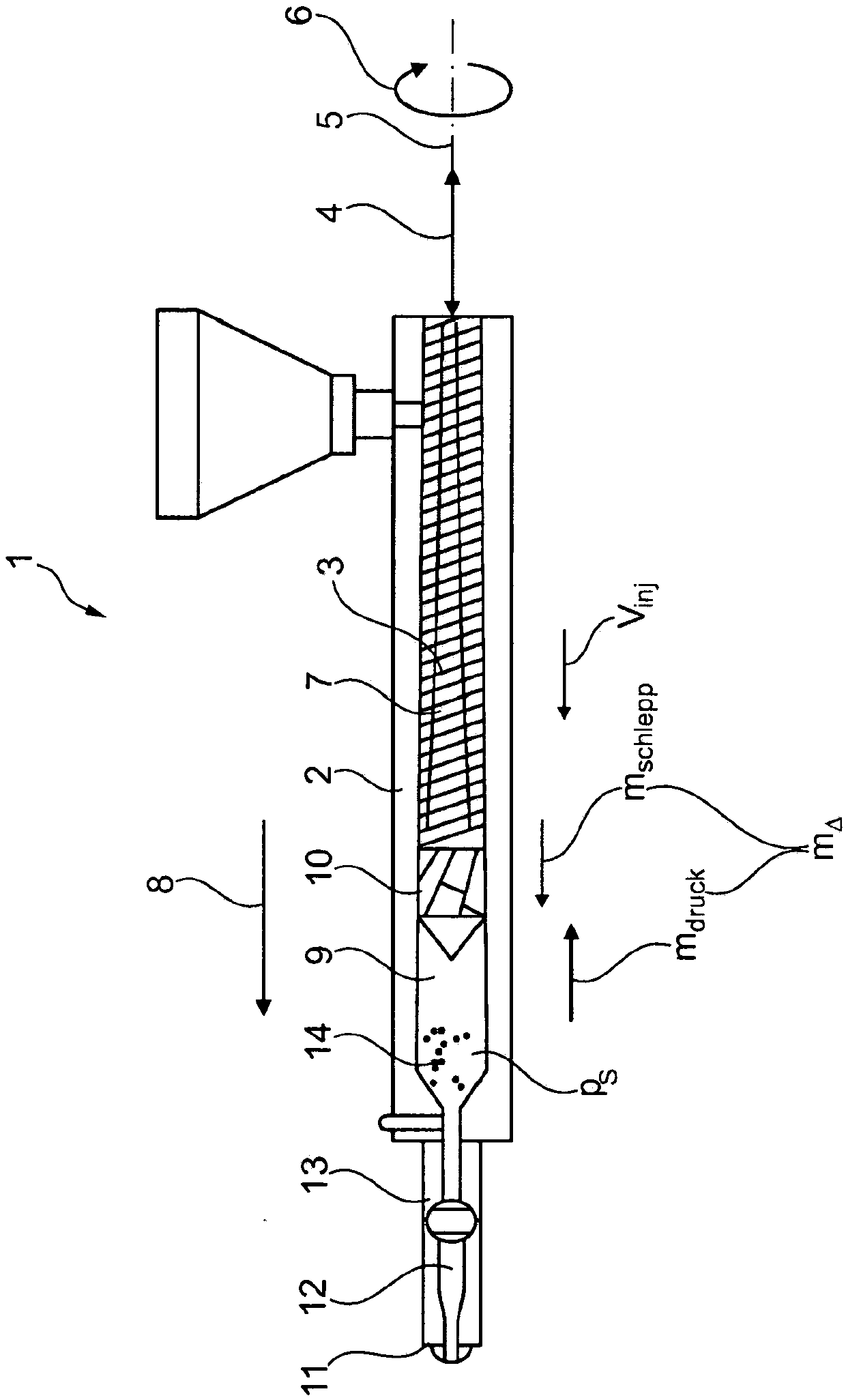
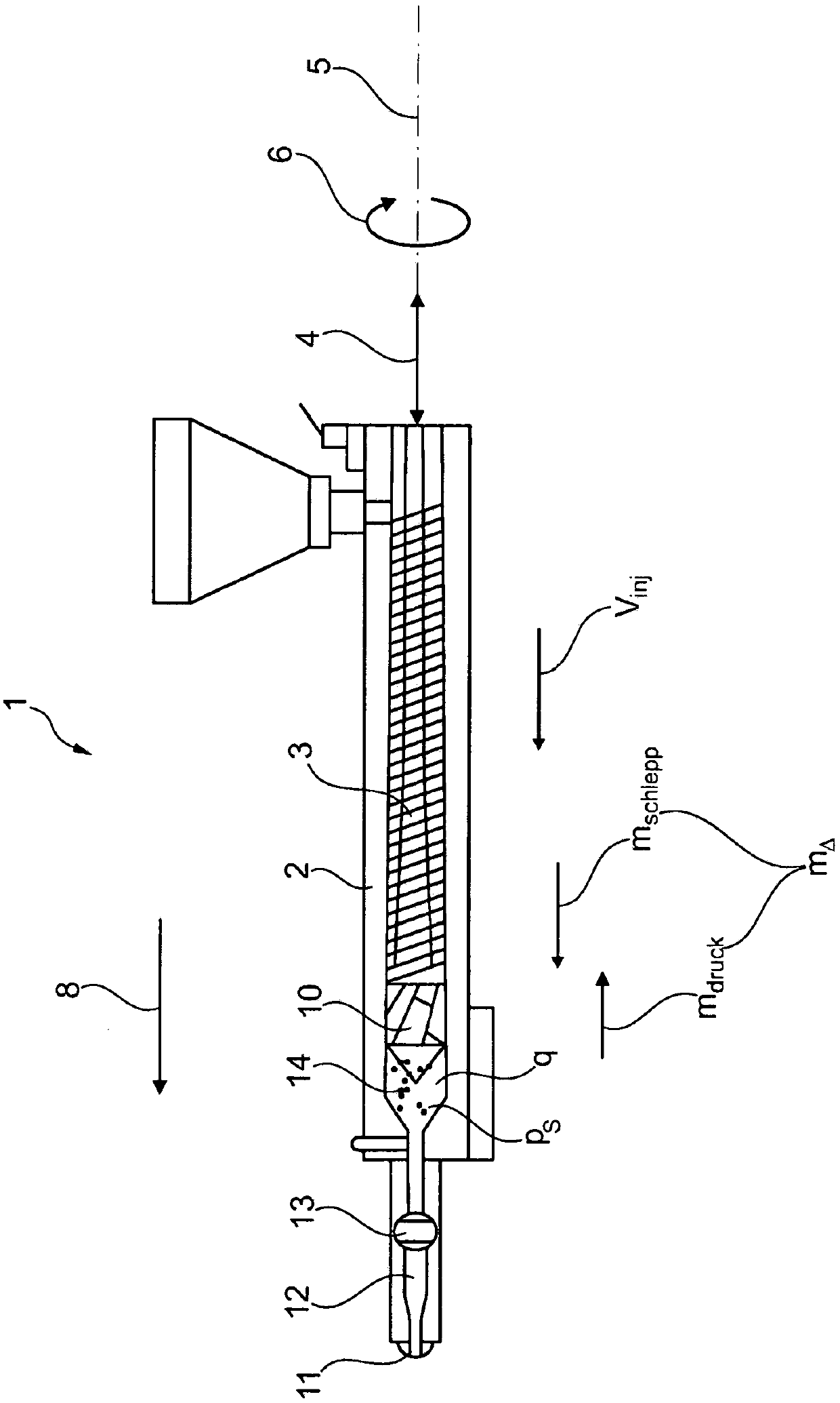
[0088] An injection molding machine 1 (injection molding machine) to which the method according to the invention can be applied has a plasticizing cylinder 2 in which a plasticizing screw 3 is arranged in a known manner. The plasticizing screw 3 can be translated in translation by means of a first drive (not shown) at a feed rate v inj Move in reciprocating direction 4. The plasticizing screw 3 can be rotated at a rotational speed n around its longitudinal axis 5 in the direction of rotation 6 by means of a second drive (not shown). scr actively driven. Through the rotational drive in the direction of rotation 6 , the plastic material within the screw flight 7 is conveyed in the conveying direction 8 to the screw antechamber 9 . The plasticizing screw 3 has a screw head 10 at its end facing the screw antechamber 9 . Backflow lockout is not set. The plasticizing cylinder 2 has an injection nozzle 11 on the end side, which is connected via a channel 12 to the screw antechamb...


PUM


Abstract

The invention relates to a method for operating an injection-moulding machine, having at least one plasticization device (2, 3) with at least one plasticization screw (3) which can be driven in rotation about a screw longitudinal axis (5) and so as to be movable in translation along the screw longitudinal axis (5), wherein, by way of the plasticization device (2, 3), a plastics melt (14) for injection into a mould cavity is provided in a screw antechamber (9), wherein, for the injection of the plastics melt (14) into the mould cavity, that is to say at least during an injection phase and during a follow-up pressure phase, the plasticization screw (3) is driven both in translation and in rotation by way of at least one drive device, wherein the driving of the plasticization screw (3) in rotation is performed with a rotational speed (nscr) such that a backflow (mdruck) of the melt from the screw antechamber (9) back into screw flights (71) of the plasticization screw (3) owing to a translational injection movement of the plasticization screw (3) has superposed on it an opposing delivery flow (mschlepp) effected by way of the rotation of the plasticization screw (3), wherein a flow difference (m[delta]) between backflow (mdruck) and opposing delivery flow (mschlepp) arises, and the flow difference (m[delta]) is, at least during the injection phase, influenced by influencing of therotational speed (nscr) of the plasticization screw (3), and the method is performed without using a backflow preventer.

Description

technical field [0001] The invention relates to a method for operating an injection molding machine according to the preamble of claim 1 . Background technique [0002] The task of the injection molding machine consists of discontinuous production of molded parts from preferably polymeric molding materials, wherein the molding takes place under pressure [Michaeli, W.: Einführung in die Kunststoffverarbeitung, Hanser, 2010]. To this end, firstly solid starting materials (granules, powder, etc.) are converted into a molten state in a metering stage. Due to the rotation of the plasticizing screw, the raw material is conveyed over the screw flight and compressed, so that it is melted by the introduction of frictional heat. Here, the emerging melt collects in the screw antechamber and passes a usually present backflow lock at the screw tip, i.e. a mechanical valve in the shape of a ring or a ball which, in the open state, is in the conveying direction Release the melt flow. ...

Claims


Application Information

Patent Timeline
Patent Type & Authority Applications(China)
IPC IPC(8): B29C45/47B29C45/76B29C45/50
CPCB29C45/47B29C45/76B29C2945/76933B29C2945/76545B29C2945/76859B29C2945/76862B29C2945/7619B29C2945/76381B29C2945/76384B29C2945/76006B29C45/5092B29C2945/7602B29C2945/7604B29C2945/7605B29C2945/7612B29C2945/76187B29C2945/76197B29C2945/76605B29C2945/76665B29C45/57B29C45/581B29C45/62B29C45/7646B29C45/77
Inventor R·席费尔斯S·克鲁帕S·莫泽M·布瑟J·沃特伯格
Owner KRAUSSMAFFEI TECH GMBH
Why Eureka
Try Eureka