Electric pollinator using air flow to calculate pollination amount

A pollinator and electric technology, applied in the direction of plant genetic improvement, botanical equipment and methods, applications, etc., to save pollen, shorten the response time of acceleration and deceleration, and reduce the effect of flower swing

Inactive Publication Date: 2018-03-13
NORTHWEST A & F UNIV
View PDF3 Cites 1 Cited by
  • Summary
  • Abstract
  • Description
  • Claims
  • Application Information

AI Technical Summary

Problems solved by technology

[0004] In order to overcome the deficiencies and defects in the prior art, the purpose of the present invention is to provide an electric pollinator th

Method used


Image

  • Electric pollinator using air flow to calculate pollination amount
  • Electric pollinator using air flow to calculate pollination amount
  • Electric pollinator using air flow to calculate pollination amount

Examples


Embodiment Construction

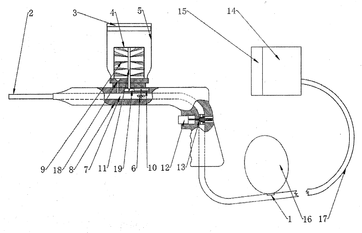
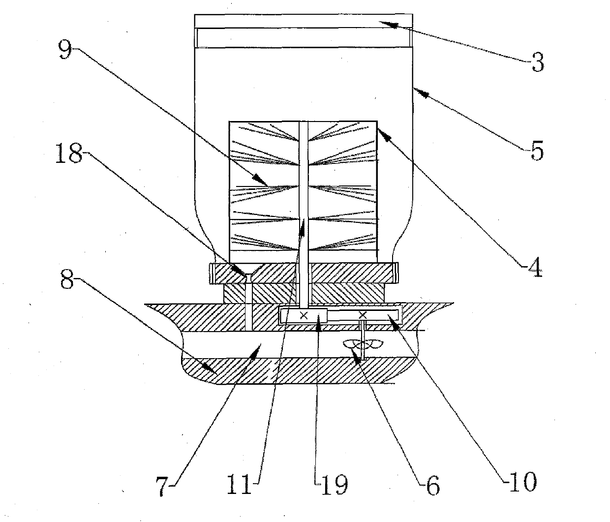
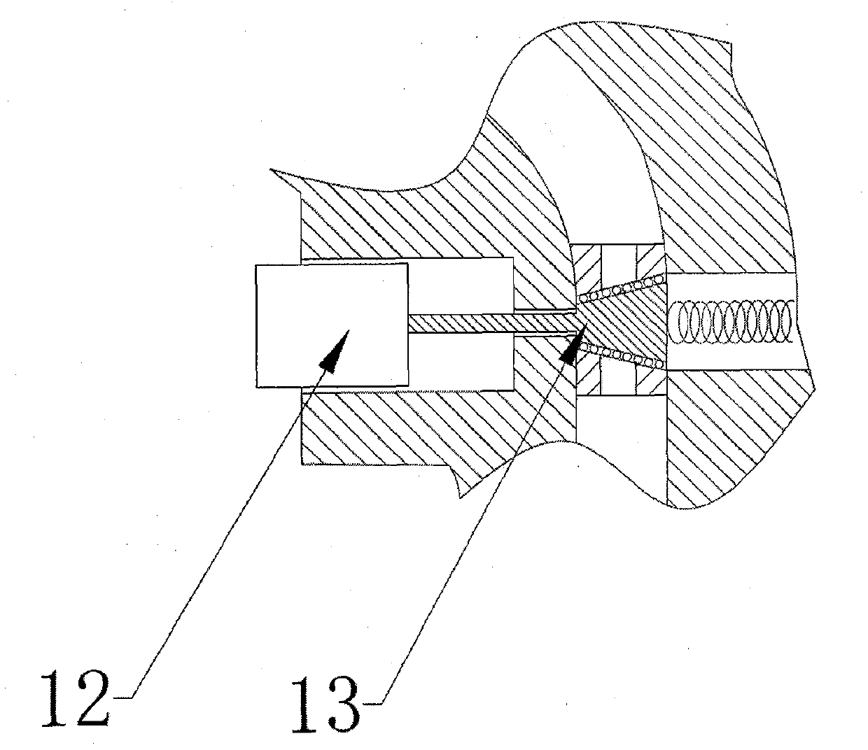
[0016] Attached below figure 1 , figure 2 A further description of the present invention: an electric pollinator for metering pollination by airflow, comprising an air pressure sensor 1, a pollination tube 2, a powder bottle cap 3, a powder leakage tank 4, a powder bottle 5, an impeller 6, and a powder spray tube 7. Housing 8, brush 9, impeller gear 10, rotating shaft 11, push switch 12, wedge valve 13, air pump 14, battery 15, air bag 16, air pipe 17, powder supply port 18, brush gear 19. It is characterized in that: the air pressure sensor 1 is fixed at the inlet of the air bag 16, the air pump 14 and the wedge valve 13 are connected to both ends of the air pipe 17, the air bag 16 is connected in the middle of the air pipe 17, and the wedge valve 13 is fixed on the housing 8, both ends of the wedge valve 13 are connected with the powder spraying pipe 7 and the air pipe 17, the push switch 12 is fixed on the housing 8, the rear end of the push switch 12 is connected with th...


PUM


Abstract

The invention discloses an electric pollinator using air flow to calculate the pollination amount, and aims to solve the problem that the pollen-ejection air flow and supplied pollen amount cannot beproportionally arranged and the pollination amount cannot be effectively metered. The air control part of the electric pollinator can maintain a stable ejection pressure and mainly comprises an air pressure sensor (1), a wedge valve (13), an air pump (14), and an airbag (16). The pollen metering part of the electric pollinator can mix pollen and air flow according to a determined ratio based on the pollen-ejection air flow and mainly comprises a pollen leaking tank (4), an impeller (6), a hairbrush (9), a gear (10), and a pollen supply opening (18). The pollen spraying time can be controlled by a press switch (12). The electric pollinator has the advantages that the pollen amount can be effectively metered by the ejection air flow, the pollen concentration of pollination air flow is maintained during the ejection process, a reasonable air pressure is maintained in an air pipe (17); and the responding speed of the press switch (12) to the ejection air flow during the start/close processis improved.

Description

technical field [0001] The invention relates to the field of plant protection machinery, in particular to an electric pollinator for measuring the amount of pollen pollination by injecting air flow. Background technique [0002] The pollinator is an auxiliary pollination device that attaches the pollen collected earlier to the pistil, which can help florists and fruit growers to quickly complete the plant pollination process. In the auxiliary pollination process, the pollen is passively sucked into the pipeline by the airflow in the existing airflow suction type pollination device. Affected by the change of the airflow intensity, it is difficult to configure the airflow and pollen supply in proportion, and the pollination amount cannot be accurately controlled; the existing pollen amount The pollination device and the jet air flow are controlled separately, the jet air flow and the pollen ration must be adjusted manually, and the ratio coordination is difficult; at the same ...

Claims


Application Information

Patent Timeline
IPC IPC(8): A01H1/02
CPCA01H1/027
Inventor 石复习朱晓文李涛石宝宝王丙龙
Owner NORTHWEST A & F UNIV
Why Eureka
Try Eureka