Eureka AIR delivers breakthrough ideas for toughest innovation challenges, trusted by R&D personnel around the world.

Umbrella stand capable of achieving automatic row changing

A technology of automatic line-wrapping and umbrella stand, which is applied in the field of umbrella stands, can solve the problems that the umbrella stand cannot be used by many people and the space is limited, and achieve the effect of saving space and avoiding water accumulation

Inactive Publication Date: 2018-03-13
华蓥市双河第三小学
View PDF0 Cites 0 Cited by
  • Summary
  • Abstract
  • Description
  • Claims
  • Application Information

AI Technical Summary

Problems solved by technology

[0004] The technical problem to be solved by this invention is that for offices or classrooms, the space is limited, and the traditional umbrella stand cannot meet the requirements for multiple people to use. Is limited, the traditional umbrella stand can not meet the requirements of many people to use the problem

Method used


Image

  • Umbrella stand capable of achieving automatic row changing

Examples


Embodiment 1

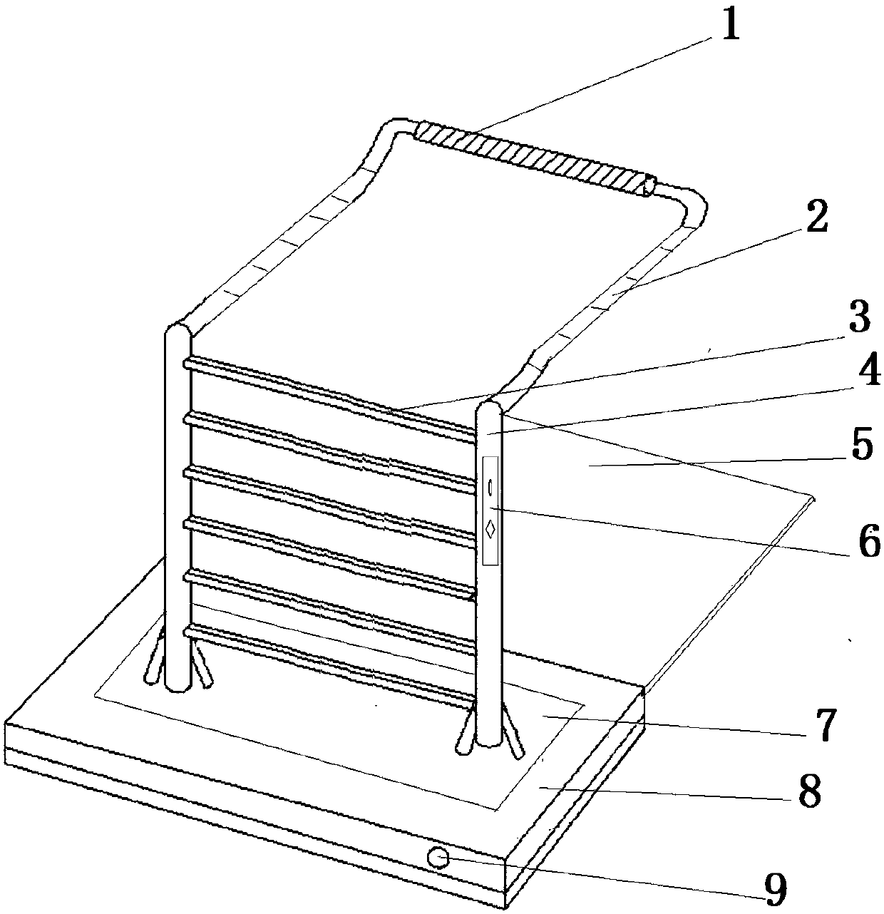
[0021] Such as figure 1 As shown, the automatic line-wrapping umbrella stand of the present invention includes a base plate mount 8, two support columns 4 are arranged on the base plate base frame 8, and a handle bar 1 is connected between the top ends of the support column 4, and the support column 4 and The joints of the handle rods 1 are provided with sliding rods 2, and the sliding rods 2 and the supporting columns 4 are perpendicular to each other; at least 5 limit holes are set on the sliding rods 2; at least 5 hanging rod brackets 3 are arranged between the two supporting columns 4 The two ends of the hanging rod support 3 are connected to the conveyor belt arranged inside the support column 4; a control module is set on any one of the support columns 4, and the control module 6 includes a lifting button; the hanging rod support 3 is provided with a fan handle hole, The number of the umbrella handle holes is at least 6.

[0022] When working: the conveyor belt is set i...

Embodiment 2

[0024] Such as figure 1 As shown, the automatic line-wrapping umbrella stand of the present invention includes a base plate mount 8, two support columns 4 are arranged on the base plate base frame 8, and a handle bar 1 is connected between the top ends of the support column 4, and the support column 4 and The joints of the handle rods 1 are provided with sliding rods 2, and the sliding rods 2 and the supporting columns 4 are perpendicular to each other; at least 5 limit holes are set on the sliding rods 2; at least 5 hanging rod brackets 3 are arranged between the two supporting columns 4 The two ends of the hanging rod support 3 are connected to the conveyor belt arranged inside the support column 4; a control module is set on any one of the support columns 4, and the control module 6 includes a lifting button; the hanging rod support 3 is provided with a fan handle hole, The number of the umbrella handle holes is at least 6. It also includes a water receiving tank 5 that is...


PUM


Abstract

The invention discloses an automatic line-wrapping umbrella stand, which includes a bottom plate seat frame, two support columns are arranged on the bottom plate seat frame, a handle bar is connected between the top ends of the support column, and the joints of the support column and the handle bar are all arranged A sliding rod, the sliding rod and the support column are perpendicular to each other; at least 5 limit holes are set on the sliding rod; at least 5 hanging rod brackets are arranged between the two supporting columns; both ends of the hanging rod bracket are connected to the supporting column An internal conveyor belt; a control module is arranged on any one of the support columns, and the control module includes a lift button; the hanging rod bracket is provided with fan handle holes, and the number of the umbrella handle holes is at least 6. It also includes a water receiving tank with the same length as the sliding rod, and the water receiving tank is slidably connected to the bottom of the base frame. It also includes a water storage tank, the water storage tank is arranged on the base frame, and the bottoms of the support columns are all located in the water storage tank. The number of holes in the umbrella is 8.

Description

technical field [0001] The invention relates to an umbrella stand, in particular to an automatic line-wrapping umbrella stand. Background technique [0002] The umbrella stand is a shelf used to store umbrellas. Generally, there are 12 umbrella positions and 18 umbrella positions. There are keys on the umbrella positions. It is generally used in large shopping malls, supermarkets, or office places. You can lock your own umbrella , Then take the key away, and when you want to leave, use the key to unlock and take away your own umbrella. [0003] For offices or classrooms, space is limited, and traditional umbrella stands cannot meet the requirements for multiple people to use. Contents of the invention [0004] The technical problem to be solved by this invention is that for offices or classrooms, the space is limited, and the traditional umbrella stand cannot meet the requirements for multiple people to use. It is limited, and the traditional umbrella stand cannot meet t...

Claims


Application Information

Patent Timeline
IPC IPC(8): A47G25/12A45B25/28
CPCA47G25/12A45B25/28
Inventor 张洪
Owner 华蓥市双河第三小学
Why Eureka
Eureka Blog
Learn More