Electric pressure cooker and uncovering device thereof

An electric pressure cooker and lid-opening device technology, which is applied in the field of kitchen utensils, can solve the problems of large movement space, easy jamming, and large stroke of the mechanism, and achieves the effect of small movement space, avoiding large movement stroke and smooth movement.

Pending Publication Date: 2018-03-13
FOSHAN SHUNDE MIDEA ELECTRICAL HEATING APPLIANCES MFG CO LTD
View PDF6 Cites 59 Cited by
  • Summary
  • Abstract
  • Description
  • Claims
  • Application Information

AI Technical Summary

Problems solved by technology

[0002] The existing method of opening the lid of the electric pressure cooker is that one end of the lid opening button generates a longitudinal force to form a longitudinal stroke, which is converted into a lateral displacement of the other end of the lid opening button through the limit of the rotation axis

Method used


Image

  • Electric pressure cooker and uncovering device thereof
  • Electric pressure cooker and uncovering device thereof
  • Electric pressure cooker and uncovering device thereof

Examples


Embodiment 1

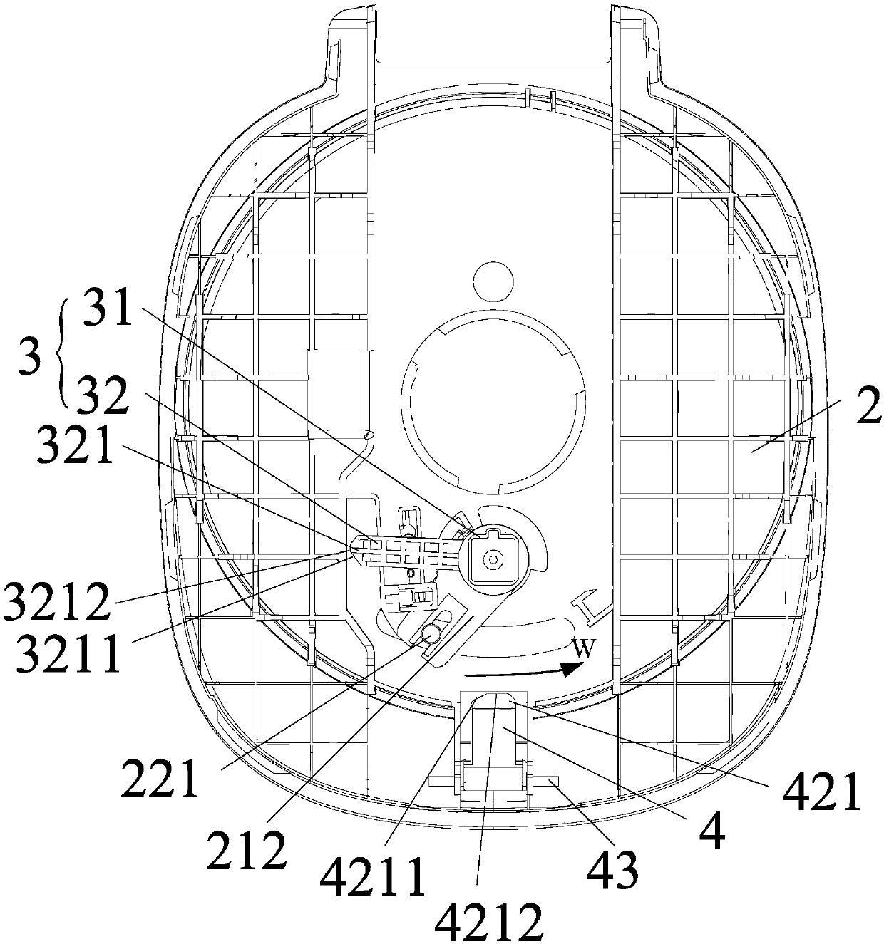
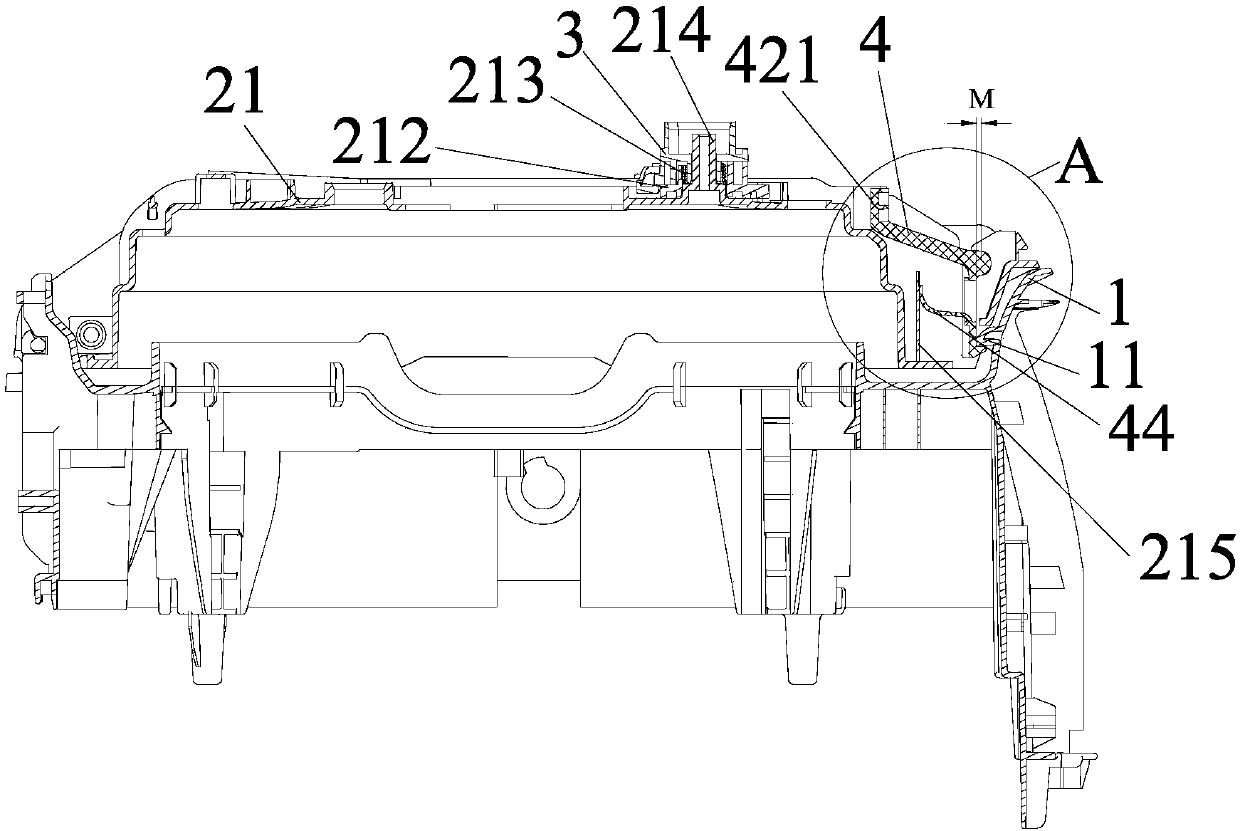
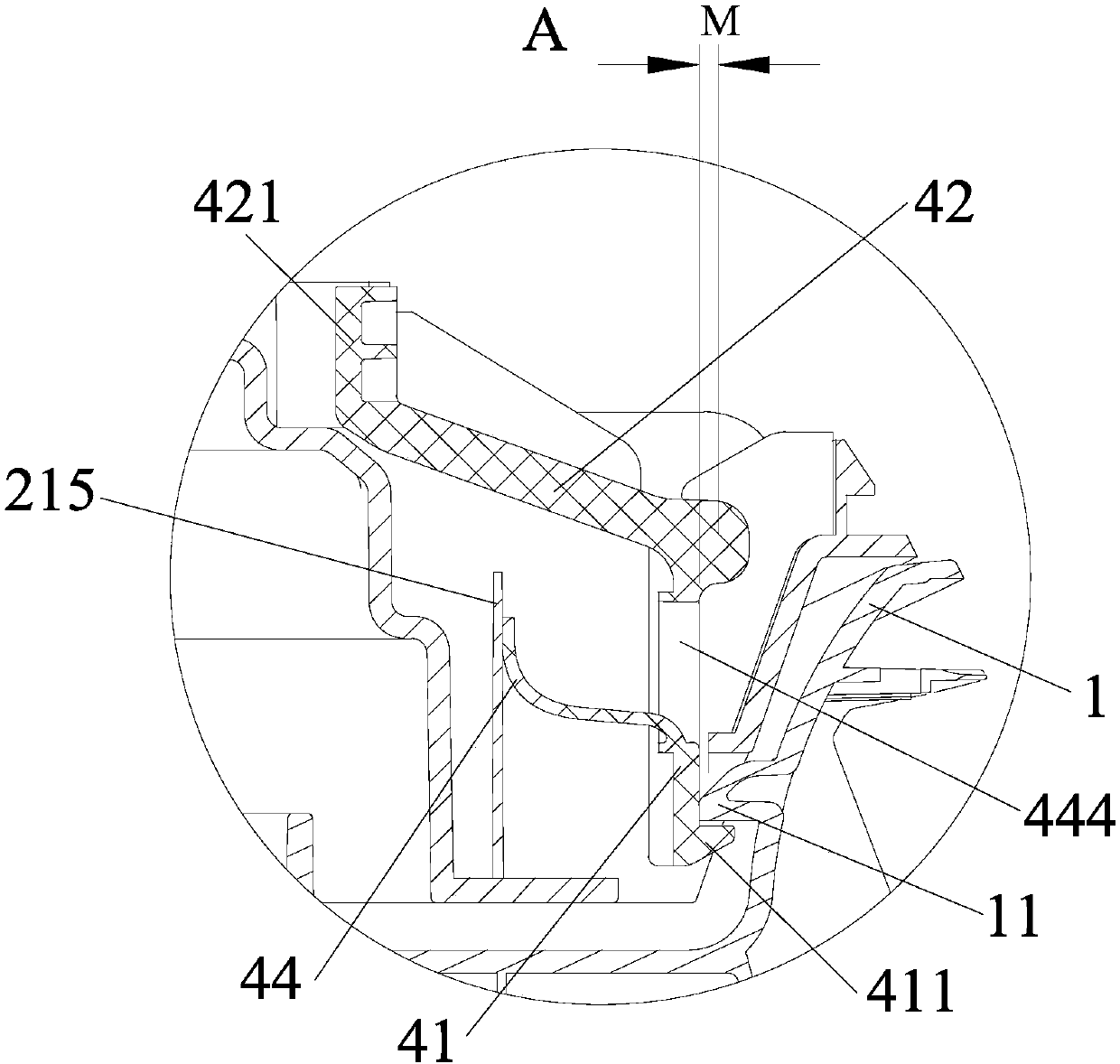
[0117] A cover opening device for an electric pressure cooker. The electric pressure cooker includes a cover body 2 and an outer cover 1. The cover body 2 includes an inner cover 21 and a pot cover 22. The cover opening device includes a transmission member 3 and a cover opening button 4. The transmission part 3 is rotatably installed on the inner cover 21, the transmission part 3 is connected with the pot cover 22, and can drive the pot cover 22 to rotate; The housing cover 1 is connected; wherein, such as Figure 4 As shown, when the transmission member 3 rotates to the first preset position, the pot teeth on the pot cover 22 are separated from the pot teeth on the outer casing 1, as Figure 5As shown, when the transmission member 3 rotates to the second preset position, the transmission member 3 abuts against the cover opening button 4 to drive the cover opening button 4 to rotate relative to the inner cover 21, so that the cover opening button 4 is in phase with the outer ...

Embodiment 2

[0164] In the first embodiment, the rib 220 is provided with a through hole matching with the rotating shaft 43 , and the rotating shaft 43 is assembled into the through hole through the deformation of the rib 220 .

[0165] The difference between embodiment two and embodiment one is that, as Figure 14 to Figure 20 As shown, the rib 220 is provided with a mounting groove 216 with an open upper end, and the rotating shaft 43 is inserted into the mounting groove 216 from the opening end of the mounting groove 216 .

[0166] The inner cover 21 is provided with a plurality of upwardly protruding ribs 220, and an installation space 221 for installing the cover-opening button 4 is defined between the two opposing ribs 220. The cover-opening button 4 is rotatably installed on the In the installation space 221, and an external force acts on the cover-opening button 4, so that when the cover-opening button 4 rotates to a set position relative to the inner cover 21, the electric pressu...


PUM

PropertyMeasurementUnit
Radiusaaaaaaaaaa

Abstract

The invention provides an electric pressure cooker and an uncovering device thereof. The uncovering device includes a driving member and an uncovering button; the driving member is rotatably arrangedon an inner cover; the driving member is connected to a cooker cover and can drive the cooker cover to rotate; the uncovering button is rotatably arranged on the inner cover through a rotation shaft,and is connected to a housing; when the driving member rotates to a first preset position, a tooth of the cooker cover is separated from a tooth of the housing; and when the driving member rotates toa second preset position, the driving member is pressed against the uncovering button so as to drive the uncovering button to rotate with respect to the inner cover, and the uncovering button is separated from the housing. According to the uncovering device, when the driving member rotates to the second preset position, the driving member generates a transverse force acting on a second end of theuncovering button so as to drive the uncovering button to rotate, and then the transverse force generated by rotation of the driving member is converted into a transverse stroke, a desired motion space is small during a rotation process of the uncovering button, and the uncovering button can move smoothly.

Description

technical field [0001] The invention relates to the field of kitchen utensils, and more specifically relates to an electric pressure cooker and a cover opening device thereof. Background technique [0002] The existing method of opening the lid of the electric pressure cooker is that one end of the lid opening button generates a longitudinal force to form a longitudinal stroke, which is converted into a lateral displacement of the other end of the lid opening button through the limit of the rotation axis of the lid opening button. This kind of lid opening method has the following disadvantages 1. Due to the longitudinal stroke, it is easy to open the cover due to human error; 2. The stroke is large, the movement space of the mechanism is large, and the movement process of the mechanism is easy to get stuck. Contents of the invention [0003] The present invention aims to solve at least one of the technical problems existing in the prior art. [0004] Therefore, an object ...

Claims


Application Information

Patent Timeline
IPC IPC(8): A47J27/08A47J27/09
CPCA47J27/08A47J27/09
Inventor 肖兵锋
Owner FOSHAN SHUNDE MIDEA ELECTRICAL HEATING APPLIANCES MFG CO LTD
Why Eureka
Try Eureka