Drainage system for fluid filter

A fluid filter and discharge system technology, applied in the field of discharge systems, can solve the problems of high manufacturing cost, high failure frequency and uncontrolled discharge system

Active Publication Date: 2018-03-13
MANN HUMMEL GMBH
View PDF8 Cites 3 Cited by
  • Summary
  • Abstract
  • Description
  • Claims
  • Application Information

AI Technical Summary

Problems solved by technology

In the first case, removal of the drain plug often results in the fluid being drained in a flush due to gravity, and this can lead to a rather uncontrolled spill to the environment and to the user's hand
In the latter case, the manufacturing cost and failure frequency of the exhaust system are high

Method used


Image

  • Drainage system for fluid filter
  • Drainage system for fluid filter
  • Drainage system for fluid filter

Examples


Embodiment Construction

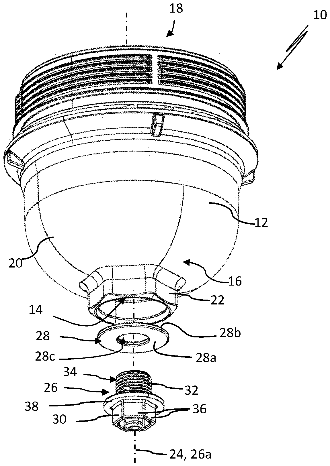
[0026] figure 1 A perspective view of a drain system 10 for fluid, in particular for draining water from the water reservoir of an oil filter or fuel filter, is shown.

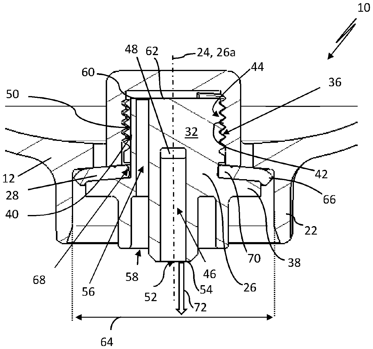
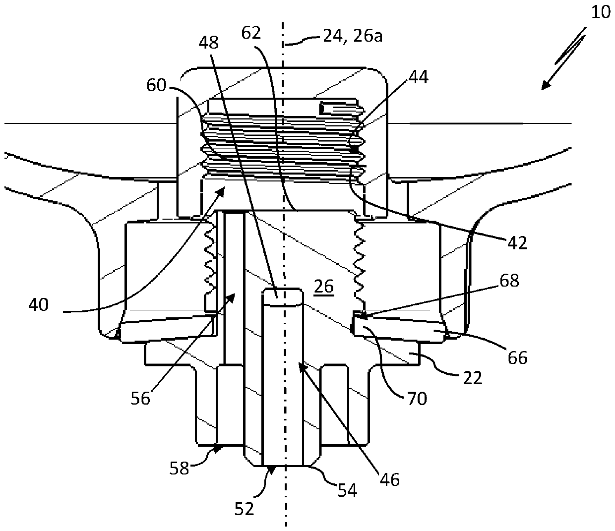
[0027] The exhaust system 10 comprises a filter housing element 12, which may be formed, for example, as a housing bowl or a housing cover of a filter housing, for eg mounting a filter element (not shown) therein. The housing element 12 is provided at its lower end 16 with a drain hole 14 for connecting the inner side 18 of the filter housing element 12 with the outer side 20 of the filter housing element 12 . On the lower end 16 of the housing element 12 a spout or collar 22 is provided. The collar 22 may protrude from the lower end 16 of the housing element 12 in an axial direction relative to the longitudinal axis 24 of the housing element 12 . Alternatively, the collar 22 can also project obliquely, in particular orthogonally, from the housing element 12 with respect to the longitudinal axis 24 of the ho...


PUM


Abstract

The invention relates to a drainage system (10), in particular for a water trap of a fuel or oil filter comprising a filter housing element (12) with a drain hole (14) for fluidly connecting an inside(18) of the housing element (12) with an outside (20) of the housing element, a drain plug (26), and a sealing ring (28) seated on the drain plug (26) for a fluid-tight closure of the drain hole. Thedrain plug is provided with a drain channel (46) and a ventilation channel (56). The sealing ring sealingly abuts against the housing element (12) in an axial and a radial direction when the drain plug (26) is positioned in its closing position; upon an axial movement of the drain plug (26) from the said closing position into a drainage position, a radially inward edge portion (70) of the sealingring (28) is dislodged from its axially sealing abutment against the filter housing (12) by the drain plug (26) while a sealing abutment of an outer edge portion (66) of the sealing ring (28) againstthe housing element (12) and a sealing abutment of a radially inward edge portion (70) of the sealing ring (28) against the drain plug (26) is maintained such that the drain hole is fluidly connectedboth to the inlet opening (48) of the drain channel (46) and the second orifice (60) of the ventilation channel (56).

Description

technical field [0001] The invention relates to a drain system for draining fluid from a fluid filter, in particular for a water trap of a fuel filter or for draining oil from an oil filter. The drain system includes a filter housing element having a drain hole for fluidly connecting the inside of the filter housing with the outside of the filter housing. There is a drain plug arranged with a longitudinal axis and a sealing ring seated on the drain plug for a fluid-tight closure of the drain hole. Background technique [0002] In practice, fluid filters such as fuel filters or oil filters are often provided with a drain system for evacuating fluid from the inside of the filter housing during maintenance work. The fluid may for example be water which has been separated from the fuel or oil during passage through the filter and which has been collected in a water reservoir inside the filter housing. Alternatively, when replacing a filter element seated inside the filter hous...

Claims


Application Information

Patent Timeline
Patent Type & Authority Applications(China)
IPC IPC(8): B01D29/92B01D33/74B01D35/30B01D35/31B01D35/153F02M37/24F02M37/32
CPCB01D29/92B01D33/74B01D35/153B01D35/30B01D35/31B01D35/16B01D36/001B01D36/003B01D36/006B01D2201/304B01D2201/34F02M35/088F02M37/24F02M37/32F01M11/0408F01M2011/0416
Inventor B.西科拉
Owner MANN HUMMEL GMBH
Why Eureka
Try Eureka