Automatic cleaning instrument of capillary viscometers

A capillary viscometer and automatic cleaning technology, applied in the direction of cleaning hollow objects, cleaning methods and utensils, chemical instruments and methods, etc. Effect

Active Publication Date: 2018-03-13
NAT INST OF METROLOGY CHINA +1
View PDF5 Cites 9 Cited by
  • Summary
  • Abstract
  • Description
  • Claims
  • Application Information

AI Technical Summary

Problems solved by technology

[0004] Therefore, the present invention provides an automatic cleaning instrument for a capillary viscometer. The cleaning instrument can automatically clean the viscometer, realize the hovering soaking and vibration cleaning of the cleaning agent at each position of the viscometer, and reduce the labor cost. , Improve work efficiency, and solve the problem of unclean cleaning by existing methods more effectively through repeated hovering, soaking and oscillation, and achieve the ideal cleaning effect

Method used


Image

  • Automatic cleaning instrument of capillary viscometers
  • Automatic cleaning instrument of capillary viscometers
  • Automatic cleaning instrument of capillary viscometers

Examples


Embodiment 1

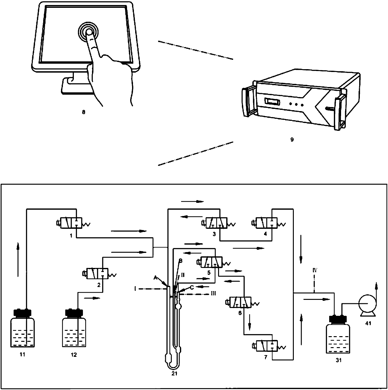
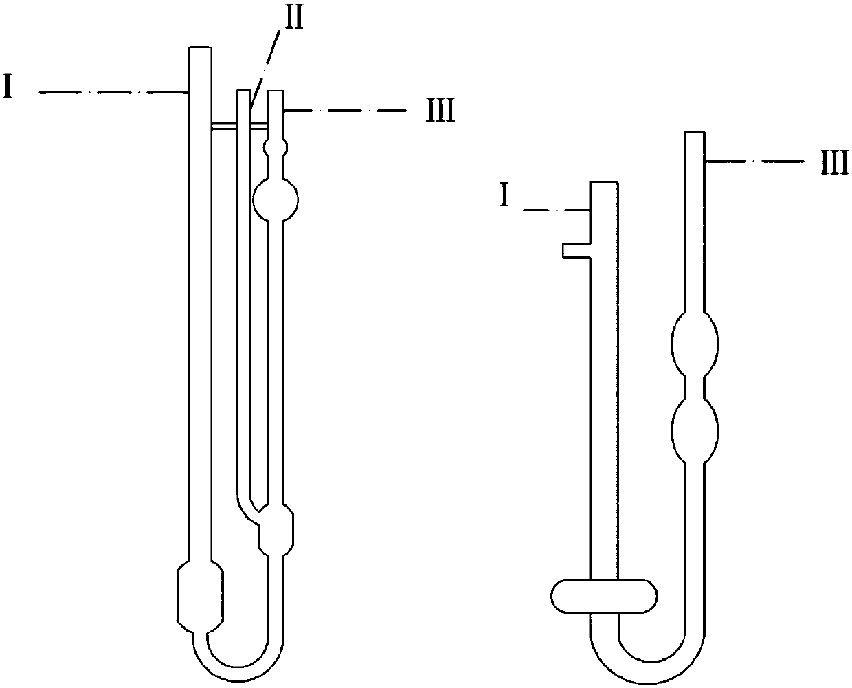
[0048] Clean the Ubbelohde viscometer: connect the wide pipe, side pipe and main pipe of the viscometer to joints A, B and C respectively. Please refer to the attached figure 1 .

[0049] Use petroleum ether only for cleaning (fill reservoir 11 with petroleum ether):

[0050] Clean the wide pipe and side pipe first:

[0051] (1) Inject solvent petroleum ether: After the program controller issues a cleaning command, solenoid valves 1 and 7 are energized and connected; solenoid valves 3 and 6 are energized and connected to the liquid circuit; solenoid valves 2 and 4 are disconnected; solenoid valve 5 is in a power-off state , the side pipe is connected to the pipeline; the vacuum pump 41 is turned on. A proper amount of petroleum ether is sucked out from the liquid storage tank 11 by negative pressure, and sucked into the side pipe through the wide pipe. When the liquid level rises to 1cm below the top of the side pipe, the sensor II receives a signal, and the solenoid valve...

Embodiment 2

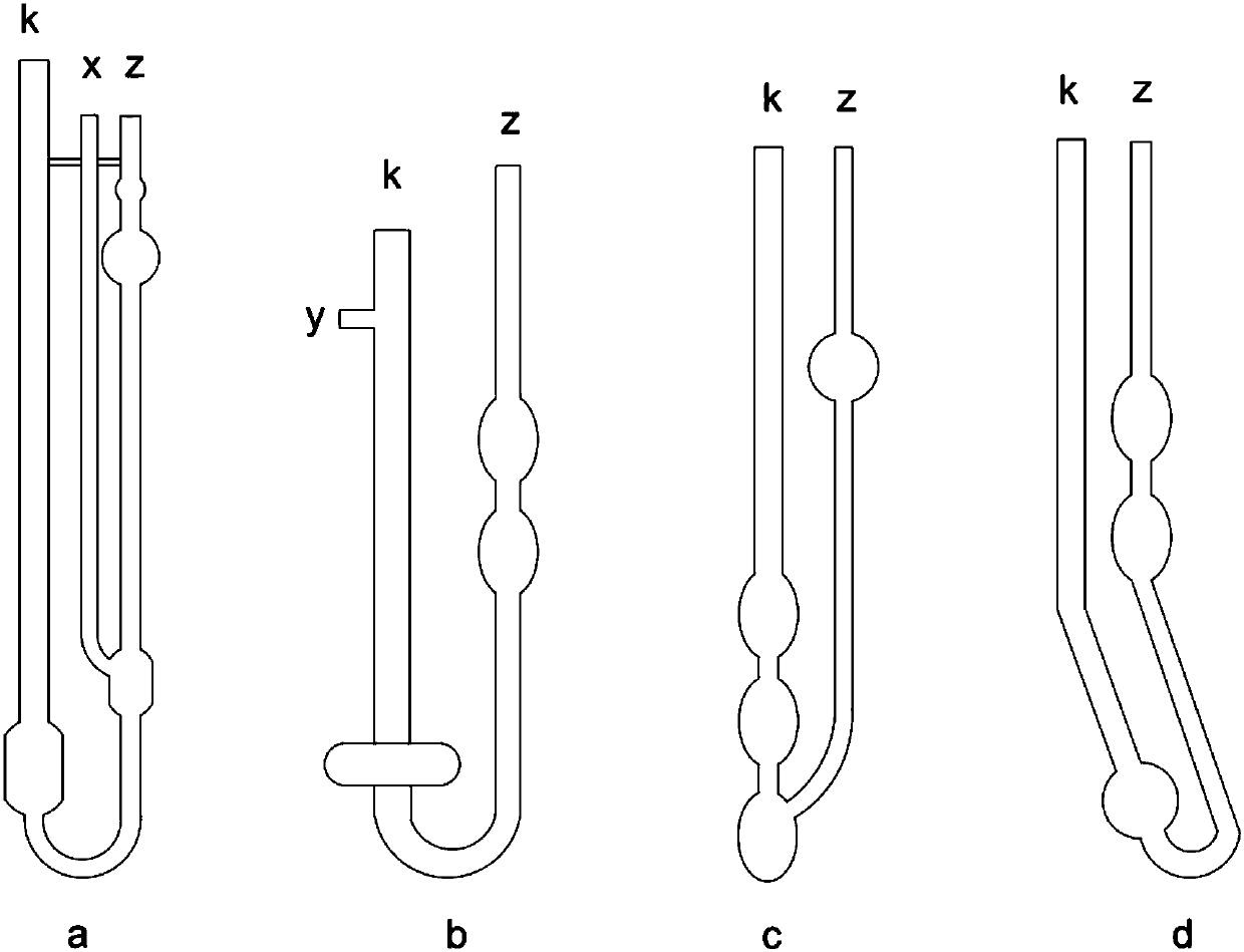
[0093] Clean the Pingshi viscometer: connect the viscometer wide pipe, branch pipe, and main pipe to joints A, B, and C respectively.

[0094] Cleaning with petrol only (fill tank 11 with petrol):

[0095] Cleaning of wide pipes and main pipes:

[0096] (25) Injecting solvent gasoline: After the program controller sends out the cleaning instruction, the solenoid valves 1 and 7 are energized and connected; the solenoid valves 3 and 6 are energized and connected to the liquid circuit; , 4 are disconnected; the vacuum pump 41 is turned on. Utilize the negative pressure to suck out a proper amount of gasoline from the liquid storage tank 11, and inhale the main pipe through the wide pipe. When the liquid level rises to 1cm below the top of the main pipe, the sensor III receives a signal, and the solenoid valves 1 and 7 are disconnected after a delay of 0.1s, the vacuum pump 41 is turned off, and the solvent feeding process ends.

[0097] (26) Gasoline hovering and soaking in th...

Embodiment 3

[0124] Clean the countercurrent viscometer: connect the wide tube and main pipe of the viscometer to joints A and C respectively.

[0125] Cleaning with petrol only (fill tank 11 with petrol):

[0126] Cleaning of wide pipes and main pipes:

[0127](43) Injecting solvent gasoline: After the program controller issues a cleaning instruction, solenoid valves 1 and 7 are energized and connected; solenoid valves 3 and 6 are energized and connected to the liquid circuit; , 4 are disconnected; the vacuum pump 41 is turned on. Utilize the negative pressure to suck out a proper amount of gasoline from the liquid storage tank 11, and inhale the main pipe through the wide pipe. When the liquid level rises to 1cm below the top of the main pipe, the sensor III receives a signal, and the solenoid valves 1 and 7 are disconnected after a delay of 0.1s, the vacuum pump 41 is turned off, and the solvent feeding process ends.

[0128] (44) Gasoline hovering and soaking in the main tube: After...


PUM


Abstract

The invention relates to an automatic cleaning instrument of capillary viscometers. The instrument comprises liquid storing devices for holding cleaning solvent, joints for connecting nozzles of the capillary viscometers, a collecting device for collecting waste liquid, a vacuum pumping device and multi-way electromagnetic valves, wherein one of the joints is respectively connected with the liquidstoring devices and the collecting device through pipelines; the other joints are connected with the collecting device through pipelines; the collecting device is connected with the vacuum pumping device; and the multi-way electromagnetic valves are arranged on the connecting pipelines and respectively used for controlling the liquid storing devices to inject the solvent into the to-be-cleaned viscometers and realizing the switch communication between the collecting device and the joints and between the joints which are only connected with the collecting device and the collecting device or anexternal gas circuit communicated through the electromagnetic valves. Through the control on the electromagnetic valves, the hovering soak and the repeated oscillation of the solvent in tubes of theviscometers are realized.

Description

technical field [0001] The invention relates to a cleaning device, in particular to an automatic cleaning device for a capillary viscometer, which is used for automatic cleaning of a viscometer for measuring the kinematic viscosity of ordinary liquids or petroleum products. Background technique [0002] In the field of petrochemical industry, capillary viscometer is a commonly used instrument to measure the kinematic viscosity of petroleum products. For any viscometer, after the measurement of a sample is completed, it must be cleaned before testing the next sample. At present, the main cleaning method is still manual cleaning. Manual cleaning is to use a dropper to drop or suck the solvent that is easy to dissolve the test sample into the viscometer to rinse back and forth, and then pour it out. Repeat this process until no obvious dirt exists. When the requirements are not high, it can be cleaned several times with one or two solvents. When the requirements are high, it...

Claims


Application Information

Patent Timeline
Patent Type & Authority Applications(China)
IPC IPC(8): B08B9/032
CPCB08B3/08B08B3/10B08B9/0321
Inventor 张正东张映澜牙昌凡
Owner NAT INST OF METROLOGY CHINA
Why Eureka
Try Eureka