A tool with a replaceable cutter head and the connection method between the replaceable cutter head and the cutter bar

A connection method and tool bar technology, which is applied in the field of the connection method of the tool and its exchangeable cutter head and the tool bar, can solve the problems of abnormal blade runout, difficult to control interference, abnormal blade wear, etc., and achieve uniform force surface. , The effect of small tool runout and high positioning accuracy

Active Publication Date: 2019-10-01
CHENGDU QIPING TECH CO LTD
View PDF5 Cites 0 Cited by
  • Summary
  • Abstract
  • Description
  • Claims
  • Application Information

AI Technical Summary

Problems solved by technology

[0002] In the traditional machine tool processing tool system, the general tool is divided into the tool holder and the cutter head. The cutter holder is the connecting part used to connect with the machine tool. Cutting products, because the replaceable blade will continue to wear during the cutting process, so the replaceable blade needs to be replaced frequently. The traditional method of replacing the blade is generally to directly press the blade on the connecting surface of the tool bar through the locking screw. This connection method is difficult to realize the centering connection between the blade and the tool holder, and every time the blade is replaced, it needs to be adjusted repeatedly, which seriously affects the efficiency of replacing the blade. The misalignment between the two tool holders will cause abnormal jumping of the blade rotation during the cutting process of the machine tool, which may cause abnormal wear of the blade in the slightest, and cause scrapping of the processed parts in severe cases. Therefore, the tool holder and the replaceable blade The centering positioning connection has always been a technical problem in this industry
In the prior art, the positioning of the cone surface and the cone surface, that is, positioning through the positioning method can also achieve accurate positioning, but this method has problems such as very difficult processing and difficult to control the amount of interference, and through the positioning method The attached tool is easily damaged when changing the tool head

Method used


Image

  • A tool with a replaceable cutter head and the connection method between the replaceable cutter head and the cutter bar
  • A tool with a replaceable cutter head and the connection method between the replaceable cutter head and the cutter bar
  • A tool with a replaceable cutter head and the connection method between the replaceable cutter head and the cutter bar

Examples


Embodiment

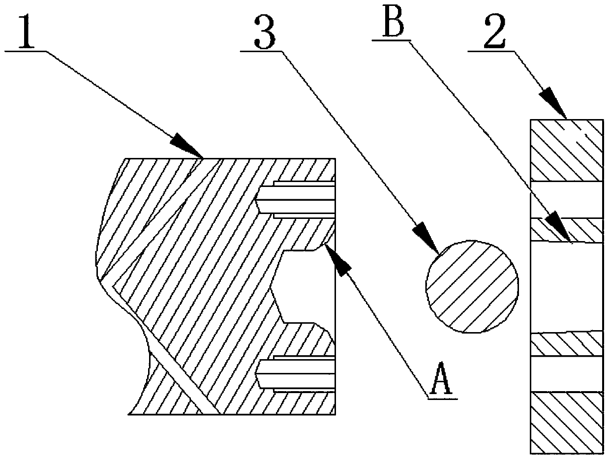
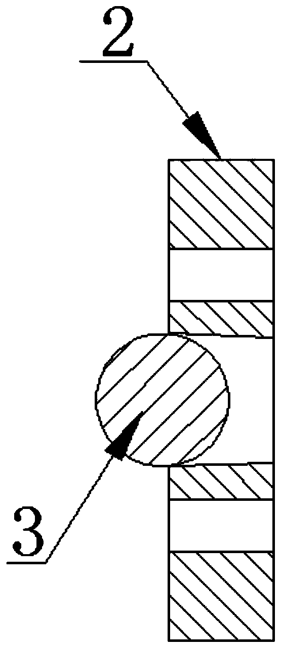
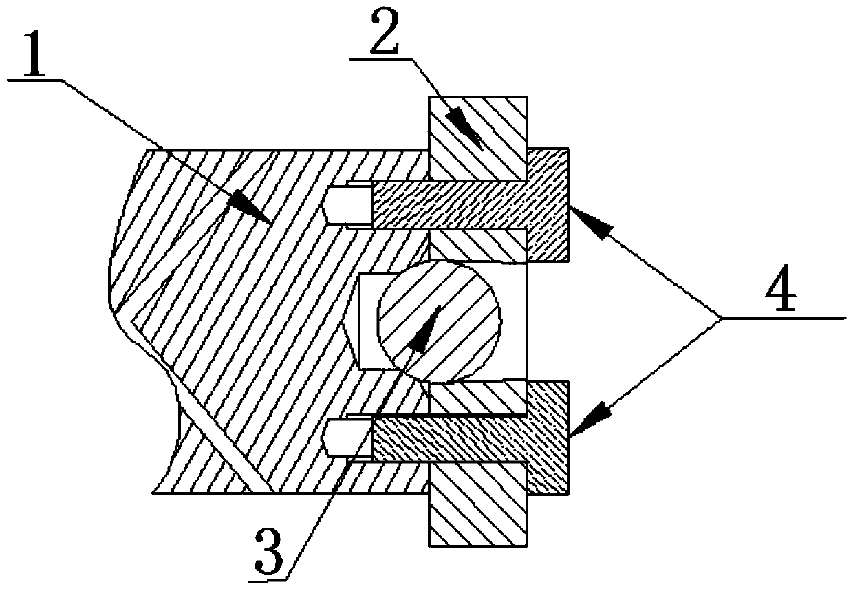
[0023] Example: such as figure 1 As shown, a cutter with a replaceable cutter head includes an inner hole with a tapered surface dug at the very center of the connecting surface of the cutter rod 1, and the angle of the taper surface of the cutter rod 1 is between 20° and 80°. ; An inner hole with a tapered surface is also excavated at the very center of the connecting surface of the replaceable blade 2, and the angle of the tapered surface of the inner hole of the replaceable blade 2 is between 1° and 8°; figure 2 As shown, a steel ball 3 is arranged in the inner hole of the replaceable blade 2; the steel ball 3 is a standard above G10, and the accuracy is within 0.001, as image 3 As shown, the steel ball 3 is pressed into the inner hole of the replaceable blade 2 with a tapered surface. There is a gap of 0.01 mm to 0.1 mm between the cutter bar 1 and the replaceable blade 2 . The connecting surface of the cutter bar 1 and the replaceable blade 2 is provided with a corres...


PUM


Abstract

The invention discloses a tool provided with a replaceable tool bit and a connecting manner of the replaceable tool bit and a tool bar of the tool. According to the tool, an inner hole having the conical surface is dug in the center of the connecting surface of the tool bar, an inner hole having the conical surface is also dug in the center of the connecting surface of a replaceable blade, and a steel ball is arranged in the inner hole of the replaceable blade; the angle of the conical surface of the inner hole of the replaceable blade ranges from 1 degree to 8 degrees; the angle of the conical surface of the tool bar ranges from 20 degrees to 80 degrees; and a gap ranging from 0.01 mm to 0.1 mm exists between the tool bar and the replaceable blade. The connecting manner comprises three steps as follows: the steel ball is mounted between the conical surface of the replaceable tool bit and the conical surface of the tool bar, and then fixation is performed by the aid of compression screws. According to the tool and the connecting manner, aligned positioning connection of the tool bar with the replaceable blade is realized, the blade can be always aligned to the cutter bar during repeated blade replacement, aligned positioning connection of the tool bar with the blade is not required to be adjusted repeatedly by wasting a lot of energy, and the runout of the whole tool can be controlled within 0.003 mm.

Description

technical field [0001] The invention relates to the field of machine tool processing, in particular to a cutter with a replaceable cutter head and a connection method between the replaceable cutter head and a cutter bar. Background technique [0002] In the traditional machine tool processing tool system, the general tool is divided into the tool holder and the cutter head. The cutter holder is the connecting part used to connect with the machine tool. Cutting products, because the replaceable blade will continue to wear during the cutting process, so the replaceable blade needs to be replaced frequently. The traditional method of replacing the blade is generally to directly press the blade on the connecting surface of the tool bar through the locking screw. This connection method is difficult to realize the centering connection between the blade and the tool holder, and every time the blade is replaced, it needs to be adjusted repeatedly, which seriously affects the efficie...

Claims


Application Information

Patent Timeline
Patent Type & Authority Patents(China)
IPC IPC(8): B23B27/16
Inventor 付强
Owner CHENGDU QIPING TECH CO LTD
Why Eureka
Try Eureka