

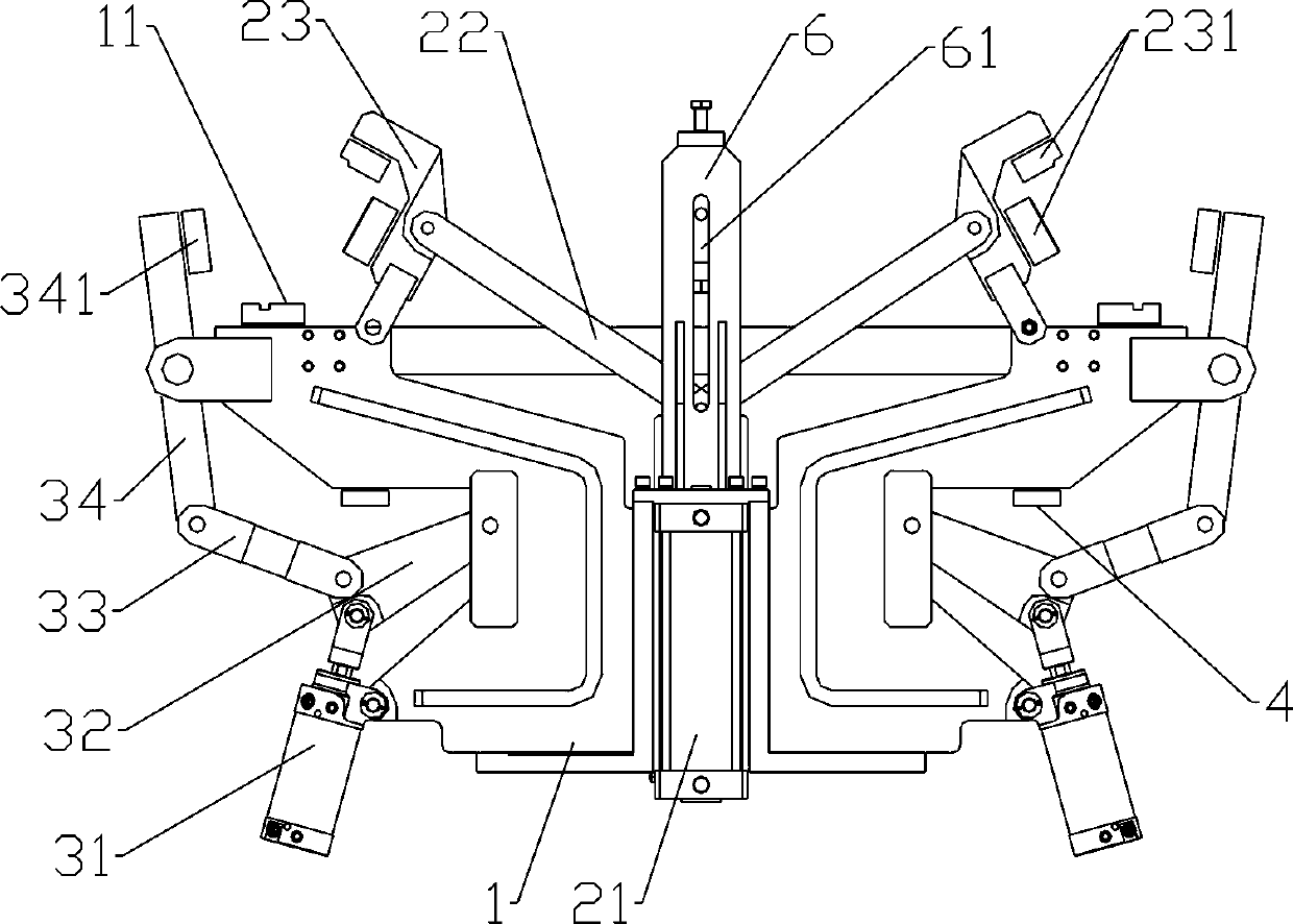
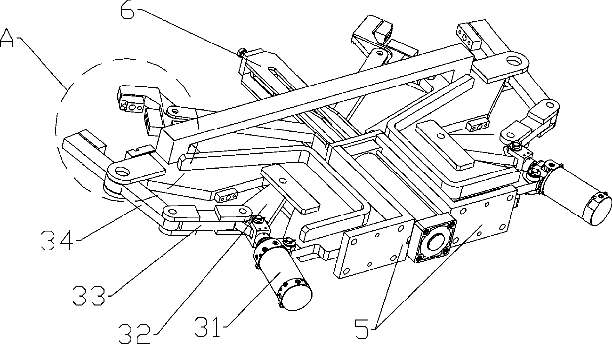
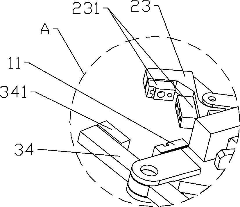
Clamping device of frame longitudinal beam
A clamping device and longitudinal beam technology, applied in auxiliary devices, vehicle parts, transportation and packaging, etc., can solve the problems of reducing output, large size deviation, slowing down production progress, etc., to avoid welding adhesion and fast clamping work. handy effect
- Summary
- Abstract
- Description
- Claims
- Application Information
AI Technical Summary
Problems solved by technology
Method used
Image

Examples
Embodiment Construction
[0019] The present invention provides a clamping device for a vehicle frame longitudinal beam. In order to make the purpose, technical solution and effect of the present invention more clear and definite, the present invention will be further described in detail below with reference to the accompanying drawings and examples. It should be understood that the specific embodiments described here are only used to explain the present invention, not to limit the present invention.
[0020] In the description of the present invention, it should be understood that the orientations or positional relationships indicated by the terms "upper", "lower", "inner", "outer", "top", "bottom" etc. are based on those shown in the accompanying drawings. The orientation or positional relationship is only for the convenience of describing the present invention and simplifying the description. In addition, the terms "first" and "second" are used for descriptive purposes only, and cannot be interprete...
PUM
 Abstract
Description
Claims
Application Information