
Clamping and moving mechanism for positioning and stamping plate raw materials of servo punching machine

A technology of moving mechanism and stamping mechanism, applied in the field of servo equipment, can solve problems such as a large amount of manpower, difficult clamping and moving, and low efficiency

Active Publication Date: 2021-09-07
江苏金沃伺服冲床有限公司
View PDF5 Cites 0 Cited by
  • Summary
  • Abstract
  • Description
  • Claims
  • Application Information

AI Technical Summary

Problems solved by technology

[0003] Servo is an automatic control system that enables the output controlled quantities of the object's position, orientation, state, etc. to follow the arbitrary changes of the input target. Before the object is stamped by the servo, it needs to be transported to the punching machine using clamping equipment. The existing ones are mainly manual. Mobile and intelligent mechanical arm movement, manual handling and movement require a lot of manpower, and the efficiency is not high, and the use of intelligent mechanical arm requires more cost. Difficult gripping movement and possible surface damage when gripping easily deformable objects like aluminum sheets

Method used


Image

  • Clamping and moving mechanism for positioning and stamping plate raw materials of servo punching machine
  • Clamping and moving mechanism for positioning and stamping plate raw materials of servo punching machine
  • Clamping and moving mechanism for positioning and stamping plate raw materials of servo punching machine

Examples


Embodiment Construction

[0030] The technical solutions in the embodiments of the present invention will be clearly and completely described below in conjunction with the embodiments of the present invention. Apparently, the described embodiments are only some of the embodiments of the present invention, not all of them. Based on the embodiments of the present invention, all other embodiments obtained by persons of ordinary skill in the art without creative efforts fall within the protection scope of the present invention.

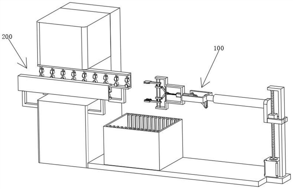
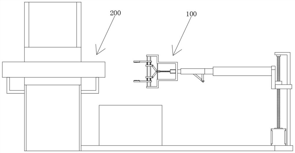
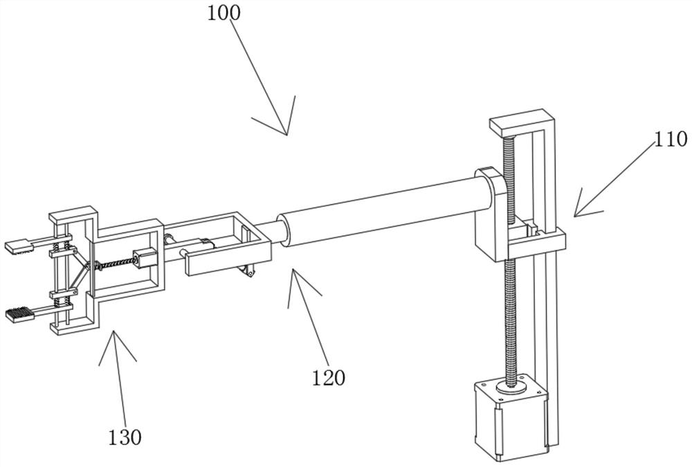
[0031] see Figure 1-8 As shown, a clamping and moving mechanism for the positioning and stamping of sheet materials by a servo punching machine includes a stamping mechanism 200. The stamping mechanism 200 includes a connecting plate 202. The top end of the connecting plate 202 is fixedly provided with a clamping and moving mechanism 100. The clamping and moving mechanism 100 It includes a lifting unit 110 for height adjustment, a turning unit 120 for adjusting the angle is fixed...


PUM


Abstract

The invention relates to the technical field of servo equipment, and specifically relates to a clamping and moving mechanism for positioning and stamping plate raw materials of a servo punching machine. The clamping and moving mechanism comprises a stamping mechanism, the stamping mechanism comprises a connecting plate, and the clamping and moving mechanism is fixedly arranged at one end of the top of the connecting plate. In the clamping and moving mechanism, the height of the clamping and moving mechanism is adjusted through a lifting unit, and therefore the plate raw materials can be conveniently clamped and moved. A reversing unit is arranged on one side of the lifting unit, a clamping unit can be driven to move through a cylinder in the reversing unit, and therefore the raw materials and the like can be moved into the servo punching machine. A rotating arm connected with the clamping unit can be driven to rotate by a certain angle through extension and retraction of an electric telescopic rod, and therefore the angle of the clamping unit can be adjusted to clamp and move raw material plates, the clamping work of a workpiece can be conveniently completed, the characteristic of dynamic adjustment is achieved, use performance is high, the structure is simple, and layout is reasonable. Manufacturing and maintenance cost is low, and the clamping and moving mechanism is suitable for application and popularization.

Description

technical field [0001] The invention relates to the technical field of servo equipment, in particular to a clamping and moving mechanism for positioning and punching sheet material of a servo punch press. Background technique [0002] The servo punching machine uses the servo motor as the direct power source, and converts the driving force generated by the motor into the linear motion of the slider through the screw, crank connecting rod, toggle rod, etc., and uses the programmable control characteristics of the servo motor to achieve perfect control The movement form of the slider is to meet the diverse and intelligent needs of stamping processing. It has the advantages of controllable slider speed, easy manufacture of difficult-to-form materials, energy saving and environmental protection, one machine with multiple functions and intelligence. It is currently recognized as the third-generation punch press. , is the mainstream trend of stamping industry development. [0003...

Claims


Application Information

Patent Timeline
IPC IPC(8): B21D43/00B21D43/11B21D43/09B21D43/02
CPCB21D43/003B21D43/11B21D43/09B21D43/026Y02P70/10
Inventor 金玉宏金泽好马铁柱朱标潘金铭陈义樊敏杰
Owner 江苏金沃伺服冲床有限公司
Learn More