
Centering system and method for three-dimensional printing equipment jetting head and numerical control equipment tool

A numerical control equipment, three-dimensional printing technology, applied in metal processing equipment, manufacturing tools, coating devices, etc., can solve the problem that the tool setting instrument cannot be used directly, the printing nozzle is fragile, and it takes a lot of time and energy to achieve Solve calibration problems, simple design, long service life effect

Active Publication Date: 2018-03-13
XIDIAN UNIV
View PDF4 Cites 6 Cited by
  • Summary
  • Abstract
  • Description
  • Claims
  • Application Information

AI Technical Summary

Problems solved by technology

[0003] To sum up, the problems existing in the existing technology are: ①When the working platform of the equipment is movable or detachable, the origin or center of the working platform often needs to be calibrated multiple times; The method in the middle method is complicated to operate, not only takes a lot of time and energy, but also the accuracy is not very high; ③At the same time, because the print nozzle itself is fragile and cannot directly contact the workpiece and the turntable, the ordinary tool setting instrument cannot be used directly

Method used

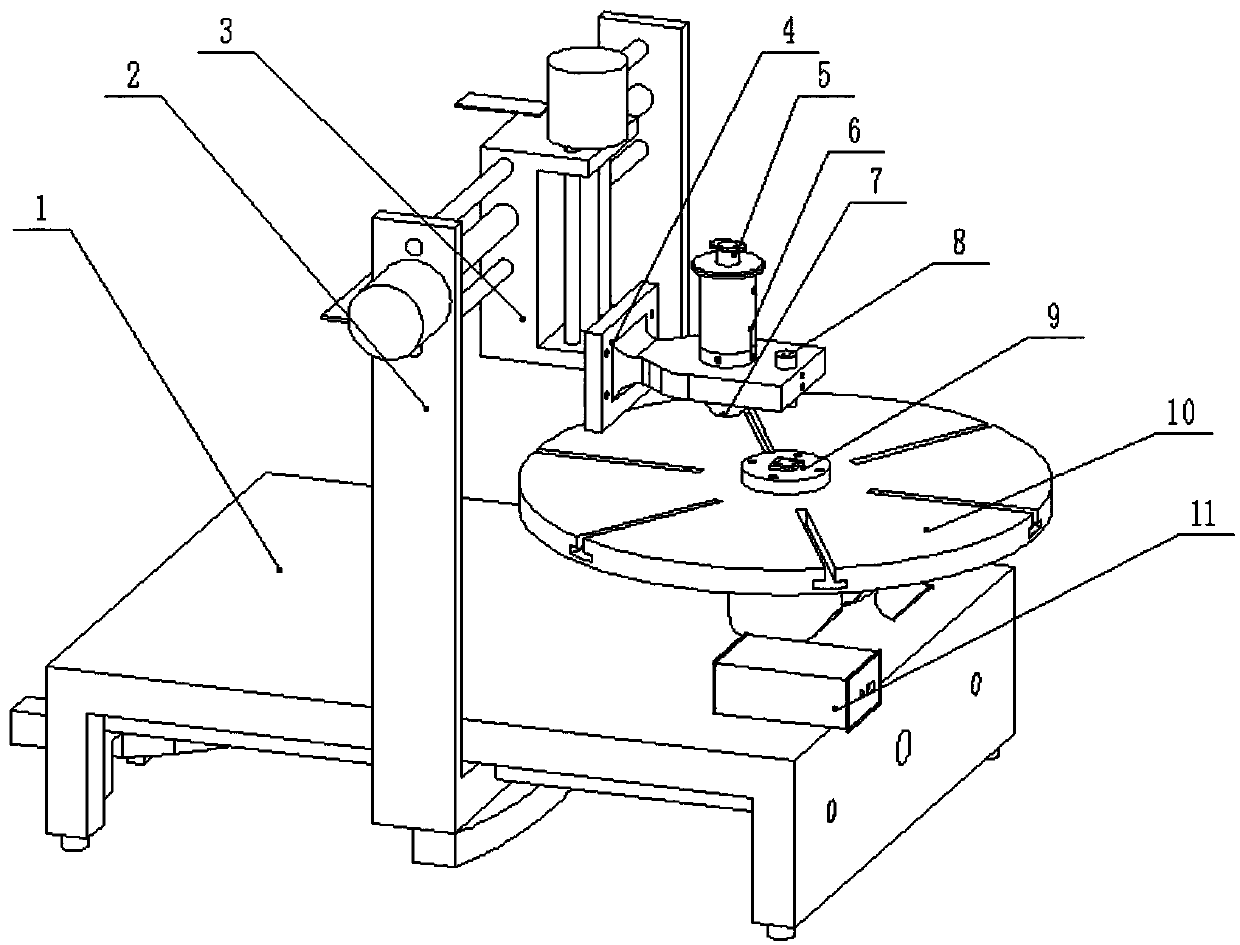

Image

  • Centering system and method for three-dimensional printing equipment jetting head and numerical control equipment tool
  • Centering system and method for three-dimensional printing equipment jetting head and numerical control equipment tool
  • Centering system and method for three-dimensional printing equipment jetting head and numerical control equipment tool

Examples


Embodiment Construction

[0020] In order to make the object, technical solution and advantages of the present invention more clear, the present invention will be further described in detail below in conjunction with the examples. It should be understood that the specific embodiments described here are only used to explain the present invention, not to limit the present invention.

[0021] The invention can effectively solve the Z-direction centering problem of the print head in 3D inkjet printing and the calibration problem of the XOY plane center in numerical control machining.

[0022] The application principle of the present invention will be described in detail below in conjunction with the accompanying drawings.

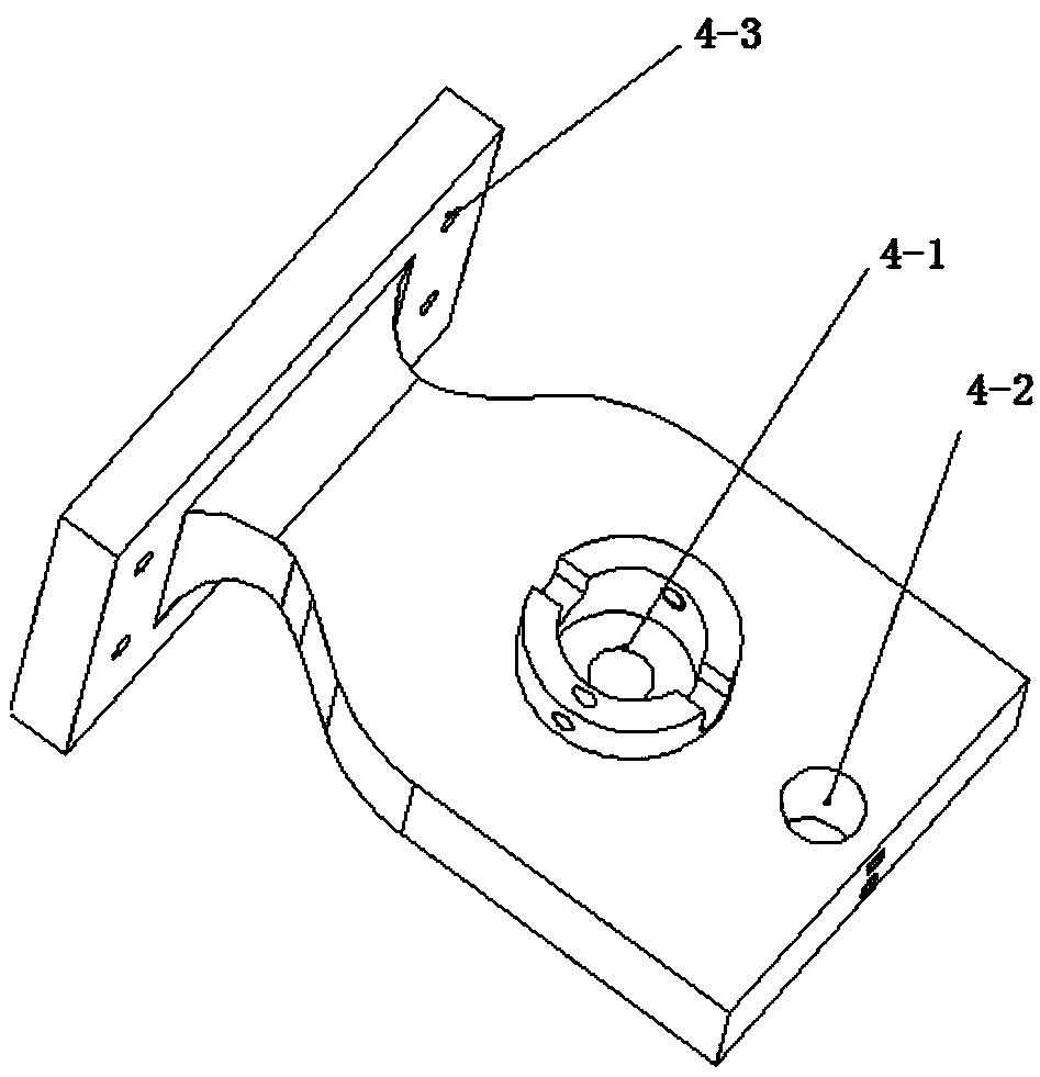
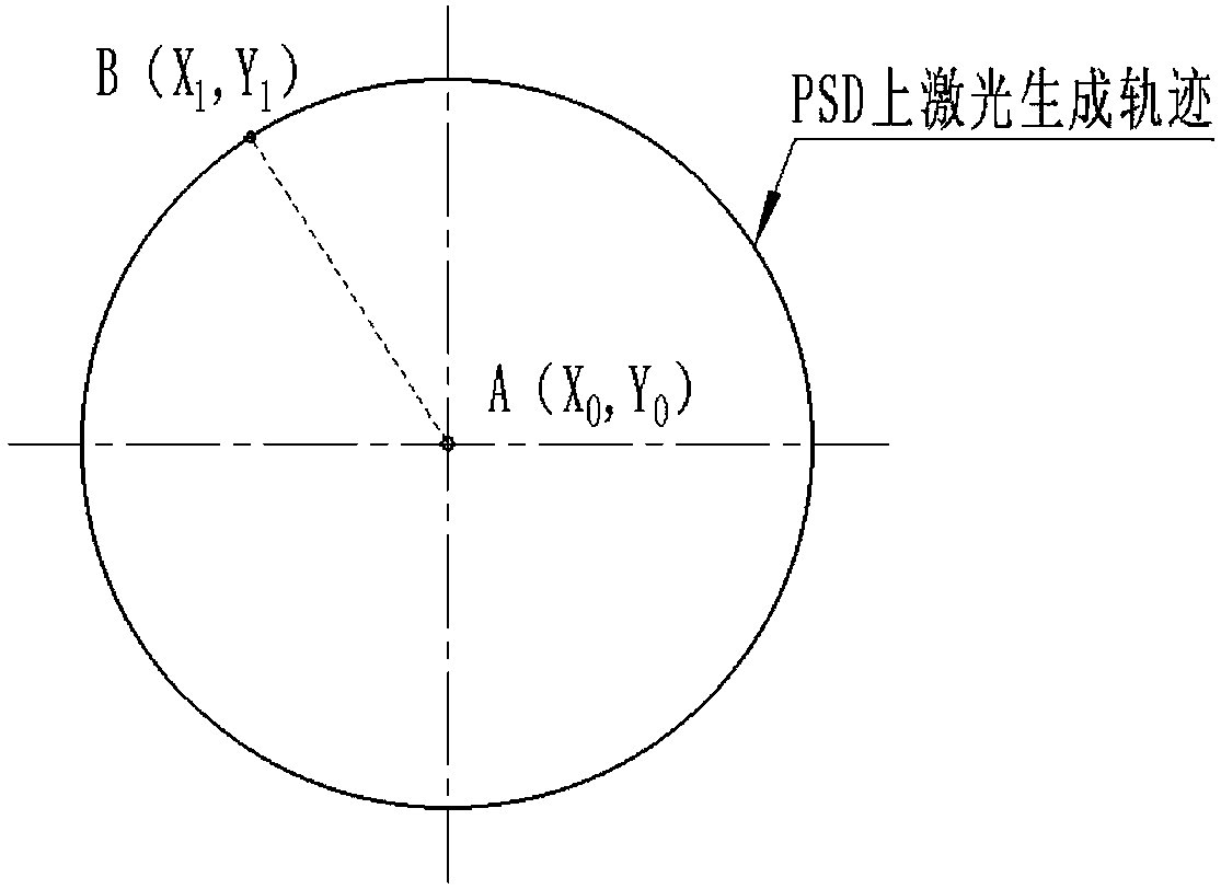
[0023] Such as figure 1 As shown, the centering system of the nozzle of the 3D printing equipment and the tool of the numerical control equipment provided by the embodiment of the present invention includes: a base 1, a gantry support 2 of the equipment, a Z axis 3 of the equipment, a ...


PUM


Abstract

The invention belongs to the fields of three-dimensional printing techniques and numerical control machining and discloses a centering system and method for a three-dimensional printing equipment jetting head and a numerical control equipment tool. A clamp support is mounted on an equipment Z shaft through mounting holes. The equipment Z shaft is provided with a laser device through a fastening bolt in a second containing hole. A two-dimensional high-precision position sensing device (PSD) is fixed to the center of an equipment C shaft working rotary table. A high-precision position sensing device (PSD) signal acquisition and processing plate is used for processing signals acquired by the position sensing device (PSD) and converting the signals into recognizable digital signals, arranged on an equipment plane and connected with the two-dimensional high-precision position sensing device (PSD) and an upper computer. By means of the centering system and method, the printing jetting head Z-direction centering problem existing in 3D ink-jet printing and the XOY plane center calibration problem in numerical control machining are effectively solved; the centering system is simple in design, ingenious in structure, good in application effect and long in serve life and serves as a PSD centering device for Z-direction centering of the 3D ink-jet printing jetting head and XOY plane tool setting in numerical control machining.

Description

technical field [0001] The invention belongs to the field of three-dimensional printing technology and numerical control processing, and in particular relates to a centering system and method for nozzles of three-dimensional printing equipment and tools of numerical control equipment. Background technique [0002] Three-dimensional printing technology is a kind of rapid prototyping technology. It is a technology based on digital model files and using bondable materials such as powdered metal or plastic to construct objects by layer-by-layer printing. With the development of 3D printing technologies such as material science, laser technology, manufacturing science and information technology, 3D printing systems and equipment are becoming more and more perfect. In the 3D printing process, there are many factors that affect the accuracy of the product, such as the accuracy of the printer itself, the performance of the material, the process parameter settings during the printing...

Claims


Application Information

Patent Timeline
Patent Type & Authority Applications(China)
IPC IPC(8): B29C64/209B29C64/153B29C64/386B23Q15/22B33Y30/00B33Y50/00
CPCB23Q15/22B33Y30/00B33Y50/00
Inventor 黄进南金政刘大川赵家勇孟凡博
Owner XIDIAN UNIV
Learn More