Underground comprehensive pipe gallery structure deeply buried in soft soil and construction method of underground comprehensive pipe gallery structure

A technology of integrated pipe gallery and pipe gallery, which is applied in the direction of underwater structures, infrastructure engineering, artificial islands, etc., can solve the problems of difficult construction, high cost, and inability to implement, so as to reduce support costs, be economical and reasonable, Simple and fast construction process

Pending Publication Date: 2018-03-13
WUHAN SURVEYING GEOTECHN RES INST OF MCC
View PDF6 Cites 3 Cited by
  • Summary
  • Abstract
  • Description
  • Claims
  • Application Information

AI Technical Summary

Problems solved by technology

However, for the "underground comprehensive pipe gallery in deep soft soil where the depth of the bottom plate is more than 10m", according to the conventional construction method, the foundation pit support is carried out first, and then the structural construction is carried out. Since the underground diaphragm wall is required in d

Method used


Image

  • Underground comprehensive pipe gallery structure deeply buried in soft soil and construction method of underground comprehensive pipe gallery structure
  • Underground comprehensive pipe gallery structure deeply buried in soft soil and construction method of underground comprehensive pipe gallery structure
  • Underground comprehensive pipe gallery structure deeply buried in soft soil and construction method of underground comprehensive pipe gallery structure

Examples


Embodiment Construction

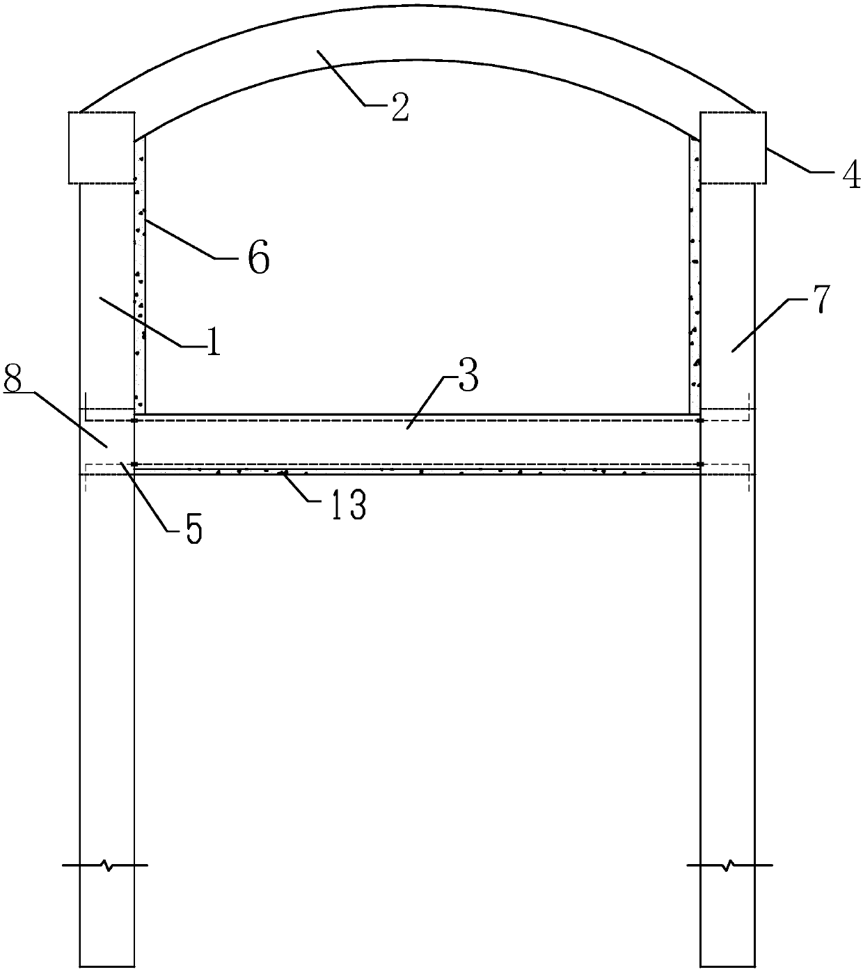
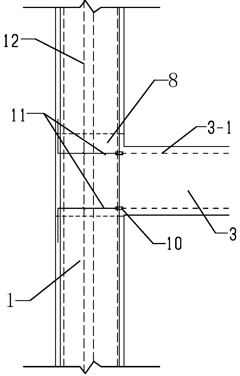
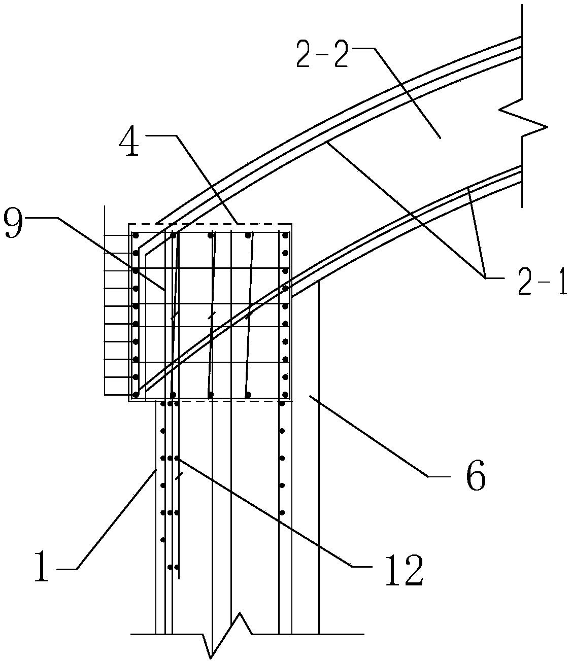
[0026] The present invention will be further described according to the above drawings. Such as figure 1 The pipe gallery structure shown is surrounded by left and right underground diaphragm walls 1 and 7 buried in deep soft soil below 10m, pipe gallery floor 3 and pipe gallery roof 2. The left and right underground diaphragm walls 1 , 7. The wall thickness is 800-1000mm, and the length is not less than 25m. Hidden beams 8 are buried at the joints between the left and right underground diaphragm walls 1, 7 and the pipe gallery bottom plate 3, and the hidden beams 8 are connected to the pipe gallery bottom plate 3 through steel bar connectors 5, as figure 2 As shown, the steel bar connector 5 is composed of an L-shaped connecting main bar 11 and a straight threaded connector 10, and the L-shaped connecting main bar 11 of each steel bar connector 5 is fixed on the steel cage 12 of the underground diaphragm wall, and Connect with one end of the straight threaded connector 10,...


PUM

PropertyMeasurementUnit
Thicknessaaaaaaaaaa
Diameteraaaaaaaaaa
Lengthaaaaaaaaaa

Abstract

The invention provides an underground comprehensive pipe gallery structure deeply buried in soft soil and a construction method of the underground comprehensive pipe gallery structure. The undergroundcomprehensive pipe gallery structure is a reinforced concrete box type structure with underground diaphragm walls buried in deep and thick soft soil 10 m below as side walls, hidden beams, top beamsand steel bar connectors are arranged on the underground diaphragm walls to be connected with a bottom plate and a top plate of a pipe gallery, and lining walls arranged in the underground diaphragm walls and the underground diaphragm walls are combined to be used as the side walls of the comprehensive pipe gallery. The elevation of the wall tops of the underground diaphragm walls is the same as that of the bottom of the top plate of the underground comprehensive pipe gallery, load-bearing bars of the top plate and wall top anchoring bars of the underground diaphragm walls are connected through the top beams, and the top plate of the comprehensive pipe gallery is formed. The hidden beams are arranged on the portions, corresponding to the bottom plate of the comprehensive pipe gallery, of the underground diaphragm walls and are connected through the steel bar connectors, and the bottom plate of the comprehensive pipe gallery is formed. According to the underground comprehensive pipe gallery structure, the problem that differential settlement is prone to being generated when the underground comprehensive pipe gallery passes through the deep and thick soft soil is solved, the foundation pit support cost is reduced, the construction process of the structure is simple, convenient and fast, and the structure is economical and reasonable.

Description

technical field [0001] The invention relates to the technical field of underground comprehensive pipe gallery engineering, in particular to an underground comprehensive pipe gallery structure buried deep in soft soil and a construction method thereof. Background technique [0002] With the continuous progress of society, underground comprehensive utility corridors have flourished all over the country. The underground comprehensive pipe gallery used for laying various urban pipe networks, its bottom plate is generally buried within 10m underground, and the structure of the comprehensive pipe gallery is a porous reinforced concrete box culvert. The common construction method is to carry out foundation pit support within 10m first , and then excavate the earthwork to the bottom of the comprehensive pipe gallery, and then carry out cushion and reinforced concrete structure construction until the underground comprehensive pipe gallery is completed. However, for the "underground ...

Claims


Application Information

Patent Timeline
IPC IPC(8): E02D29/045
CPCE02D29/10Y02E10/20
Inventor 余火忠严稳平石东晓
Owner WUHAN SURVEYING GEOTECHN RES INST OF MCC
Why Eureka
Try Eureka