
Factory waste heat utilization system

A waste heat, factory technology, applied in waste heat treatment, lighting and heating equipment, process efficiency improvement and other directions, can solve the problems of heat waste, limited thermal insulation effect, can not be effectively used, etc., to achieve the effect of efficient use

Inactive Publication Date: 2018-03-13
SHANDONG INST OF COMMERCE & TECH
View PDF4 Cites 0 Cited by
  • Summary
  • Abstract
  • Description
  • Claims
  • Application Information

AI Technical Summary

Problems solved by technology

[0002] The ceramic factory mainly produces ceramic tiles. The existing ceramic factory generally passes the gas generated by the gas station to the inside of the kiln to fire the tiles. Due to the limited heat preservation effect, a large amount of heat will be emitted from the outside of the kiln. The heat dissipates Going outside will not only increase the temperature of the employee's working environment, making the employees miserable, but also cannot be effectively used, resulting in waste of heat

Method used


Image

  • Factory waste heat utilization system
  • Factory waste heat utilization system
  • Factory waste heat utilization system

Examples


Embodiment Construction

[0016] Embodiments of the present invention are further described below in conjunction with the accompanying drawings:

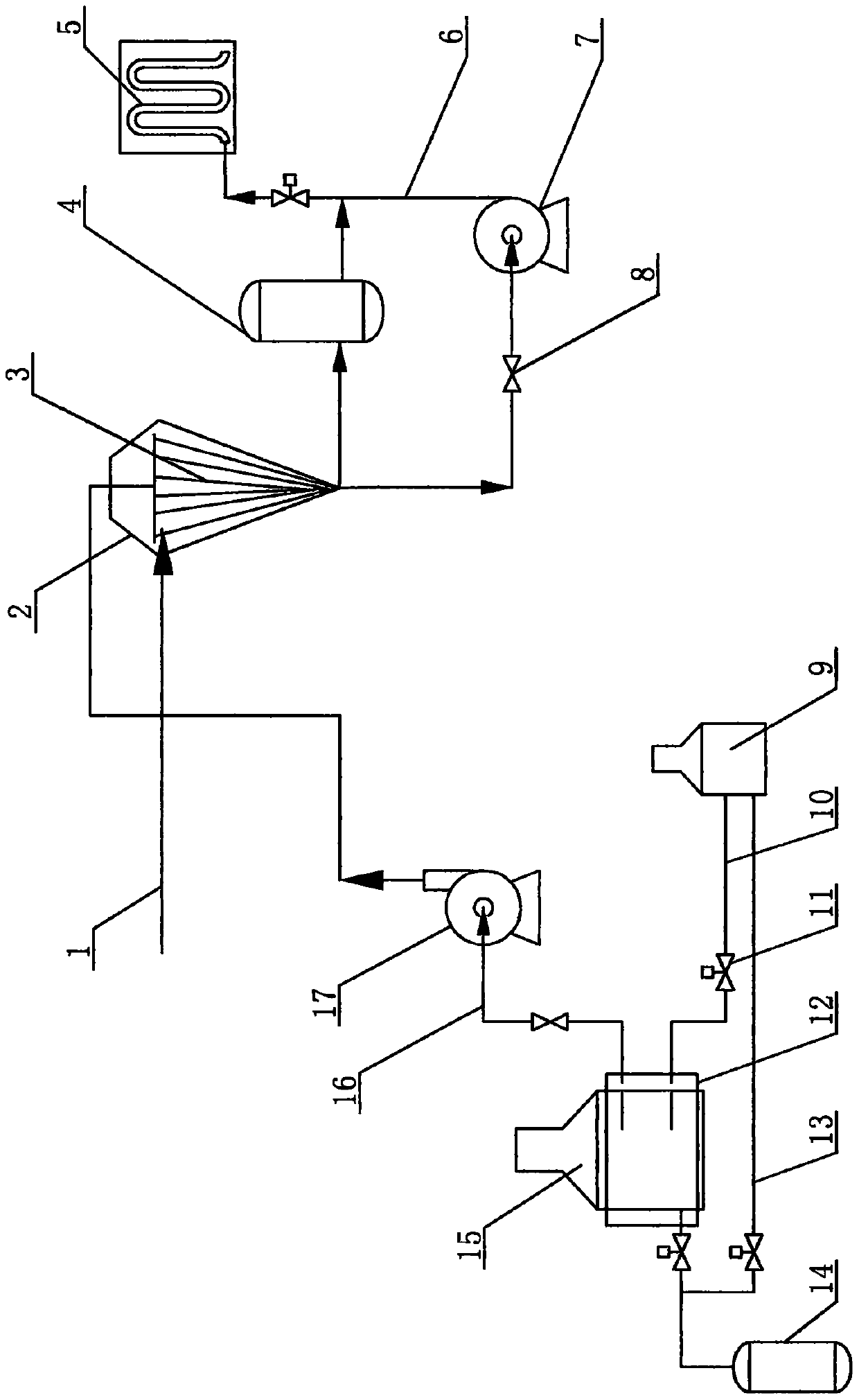
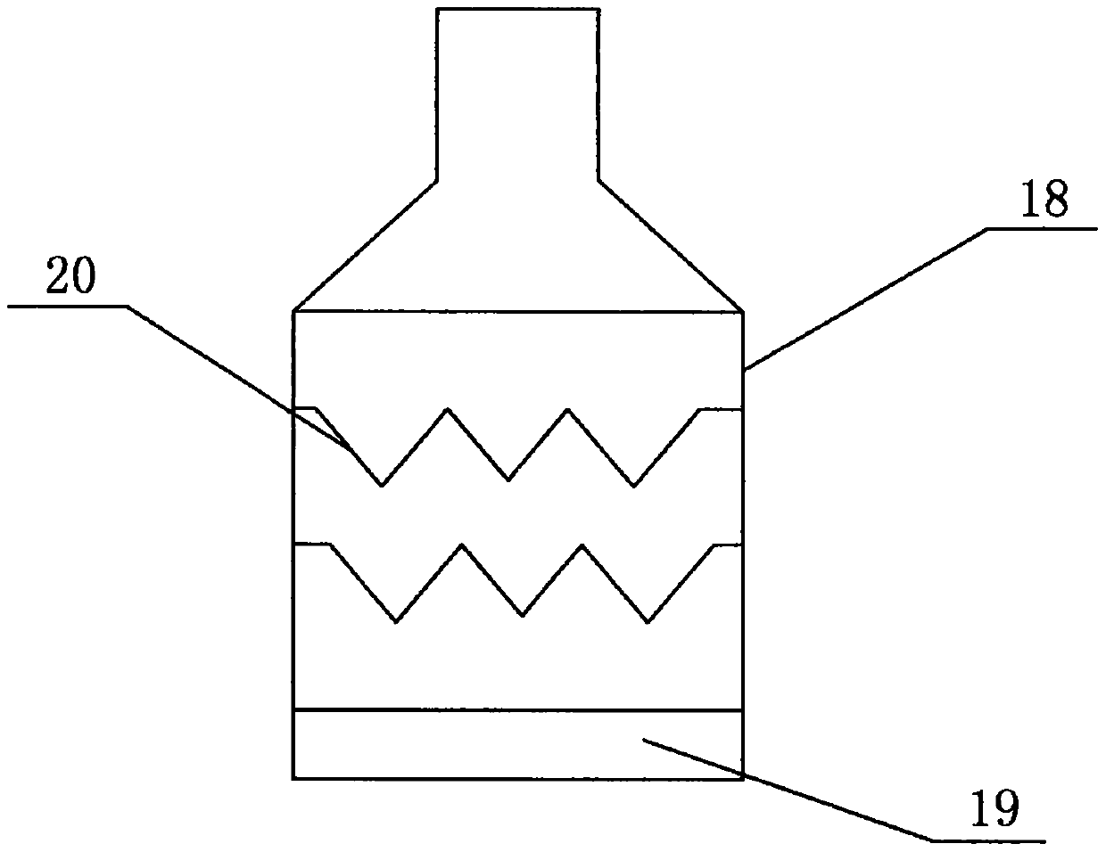
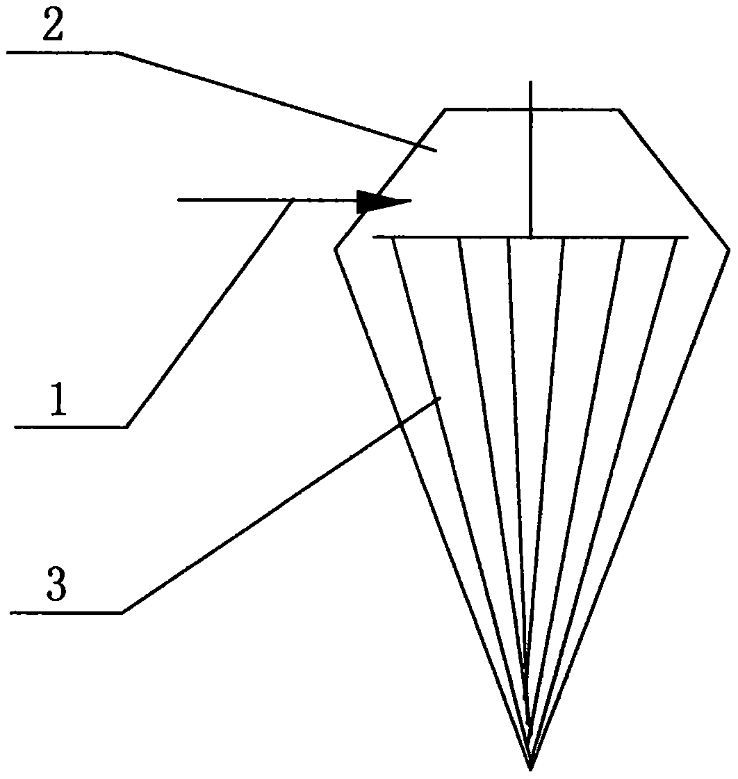
[0017] Such as Figure 1-2 As shown, the plant waste heat utilization system of the present invention includes a gas storage tank 14 and a kiln 15, and the outside of the kiln 15 is provided with a heat collecting cover 12, and the heat collecting cover 12 is respectively connected to the first hot gas pipe 16 and the second heat pipe 16. Air pipe 10, the air outlet of the first hot air pipe 16 is connected with the air intake coil 3, and the pipeline between the first hot air pipe 16 and the air intake coil 3 is provided with a stop valve 8 and an exhaust fan 17 successively, and the air intake disk The outside of the pipe 3 is provided with a water tank 2, the air outlet of the intake coil 3 is connected to the condensation tank 4, the water outlet of the condensation tank 4 is connected to the radiator 5, and the pipeline between the condensation tank 4 a...


PUM


Abstract

The invention relates to the technical field of waste heat utilization, in particular to a factory waste heat utilization system. The factory waste heat utilization system comprises a gas storage tankand a kiln. A heat collection housing is arranged at the outer side of the kiln and connected with a first hot gas pipe and a second hot gas pipe. A gas outlet of the first hot gas pipe is connectedwith a gas inlet coil. A pipeline between the first hot gas pipe and the gas inlet coil is sequentially provided with a stop valve and an exhaust fan. A water tank is arranged at the outer side of thegas inlet coil. A gas outlet of the gas inlet coil is connected with a condensation tank. A water outlet of the condensation tank is connected with a finned radiator. A solenoid valve is arranged ona pipeline between the condensation tank and the finned radiator. The water tank is connected with a water inlet pie and one end of a water outlet pipe, and the other end of the water outlet pipe is connected with the finned radiator. A pipeline of the water outlet pipe re sequentially provided with a stop valve and a pressurization pump. By means of the factory waste heat utilization system, heatcan be effectively utilized.

Description

technical field [0001] The invention relates to the technical field of waste heat utilization, in particular to a plant waste heat utilization system. Background technique [0002] The ceramic factory mainly produces ceramic tiles. The existing ceramic factories generally pass the gas generated by the gas station to the inside of the kiln to fire the tiles. Due to the limited heat preservation effect, a large amount of heat will be emitted from the outside of the kiln. The heat dissipates Going outside will not only increase the temperature of the employees' working environment, making employees miserable, but also cannot be effectively used, resulting in waste of heat. Contents of the invention [0003] In order to solve the deficiencies in the above technical problems, the object of the present invention is to provide a factory waste heat utilization system, which can effectively utilize heat. [0004] The technical scheme that the present invention adopts for solving i...

Claims


Application Information

Patent Timeline
Patent Type & Authority Applications(China)
IPC IPC(8): F27D17/00
CPCF27D17/004Y02P10/25
Inventor 张虹
Owner SHANDONG INST OF COMMERCE & TECH
Learn More