
Rapid and efficient small vessel hemostatic forceps convenient to use

A hemostatic forceps and high-efficiency technology, applied in the field of medical devices, can solve the problems of less strict disinfection, waste of medical personnel's energy, and potential safety hazards, and achieve the effect of reducing the area of ​​disinfection, reducing energy waste, and increasing the field of vision.

Inactive Publication Date: 2018-03-16
田长江
View PDF12 Cites 4 Cited by
  • Summary
  • Abstract
  • Description
  • Claims
  • Application Information

AI Technical Summary

Problems solved by technology

[0002] At present, the hemostatic forceps used in some hospitals are generally directly grasped and used by medical staff, and then the blood vessels are clamped to stop bleeding through observation with the eyes. Generally, the hemostatic forceps need to be extended into the human body for use, so it is generally necessary before use. Disinfect it as a whole, but part of it does not need to enter the human body. The disinfection here is not so strict, resulting in some waste of resources during the overall disinfection, and after the hemostat enters the human body, it is blocked and the situation cannot be seen clearly, resulting in Accidentally touch other parts of the patient, causing secondary injury to the patient, and there is a potential safety hazard. After the blood vessel is clamped, continuous force is required to ensure that the blood vessel is clamped and the blood will not be lost, which will waste part of the energy of the medical staff

Method used


Image

  • Rapid and efficient small vessel hemostatic forceps convenient to use
  • Rapid and efficient small vessel hemostatic forceps convenient to use
  • Rapid and efficient small vessel hemostatic forceps convenient to use

Examples


Embodiment Construction

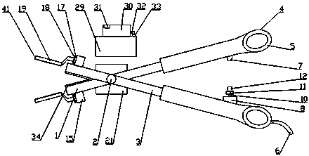
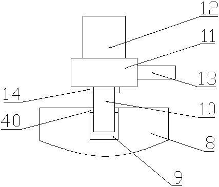
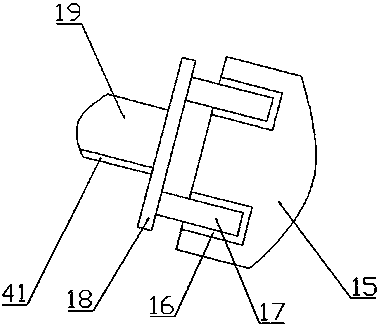
[0022] The present invention is specifically described below in conjunction with accompanying drawing, as Figure 1-6 As shown, a fast, efficient and convenient small blood vessel hemostat includes upper and lower splints 1, the middle positions of the upper and lower splints 1 are hinged together by screws 2, and a gripping mechanism is provided behind the upper and lower splints 1, and the gripping mechanism consists of The telescopic extension rod 3 fixedly connected to the end of the upper and lower splint 1, the oval finger hole 4 fixedly installed on the inner side of the end of the telescopic extension rod 3, the rubber anti-slip mat 5 fixedly installed in the oval finger hole 4, and the oval finger hole fixedly installed on the bottom The auxiliary rod 6 on the outside of the finger hole 4 is jointly formed. An auxiliary fixing mechanism is provided between the telescopic extension rods 3. The auxiliary fixing mechanism is composed of a small fixed permanent magnet 7 fi...


PUM


Abstract

The invention discloses a pair of rapid and efficient small vessel hemostatic forceps convenient to use. The pair of hemostatic forceps comprises an upper splint and a lower splint. A handheld mechanism is arranged behind the upper splint and the lower splint. The handheld mechanism is provided with stretchable extending rods, an oval finger hole, a rubber anti-skid pad and an auxiliary rod; an auxiliary fixing mechanism is arranged between the stretchable extending rods, the auxiliary fixing mechanism is provided with a small fixing permanent magnet, a small supporting table, a threaded hole,a double-screw bolt, a small containing table, a small powerful permanent magnet, a small rotary rod and a rubber pad, an extending mechanism is arranged in the front of the upper and lower splints,the extending mechanism is provided with a small fixing table, a rectangular clamping groove, a rectangular card, a connecting plate, a chuck and a micro stretchable contact, a camera shooting mechanism is arranged on the upper and lower splints, and the camera shooting mechanism is provided with a pinhole camera body, a photographing lens, a battery hole, a micro rechargeable battery, a battery stop cover, a memory card, a starting switch, a supporting table, a capacitance display screen, an electricity plug and an electricity socket. The pair of hemostatic forceps has the advantages of beingsimple in structure and high in practicability.

Description

technical field [0001] The invention relates to the field of medical instruments, in particular to a fast, efficient and convenient small blood vessel hemostat. Background technique [0002] At present, the hemostatic forceps used in some hospitals are generally directly grasped and used by medical staff, and then the blood vessels are clamped to stop bleeding through observation with the eyes. Generally, the hemostatic forceps need to be extended into the human body for use, so it is generally necessary before use. Disinfect it as a whole, but part of it does not need to enter the human body. The disinfection here is not so strict, resulting in some waste of resources during the overall disinfection, and after the hemostat enters the human body, it is blocked and the situation cannot be seen clearly, resulting in Accidentally touching other parts of the patient will cause secondary injury to the patient, posing safety hazards, and after the blood vessel is clamped, continuo...

Claims


Application Information

Patent Timeline
IPC IPC(8): A61B17/122A61B17/28A61B90/00
CPCA61B17/122A61B17/2812A61B17/282A61B90/37A61B2017/12004
Inventor 不公告发明人
Owner 田长江
Learn More