Carburized layer thickness detecting device and method

A detection method and detection device technology, applied in the direction of measuring device, electromagnetic measuring device, electric/magnetic thickness measurement, etc., can solve problems such as inadaptability to rapid inspection, trouble, etc., and achieve the effects of efficient nondestructive testing, portability, and small error

Inactive Publication Date: 2018-03-16
NINGBO YINZHOU CITAI ELECTRONICS TECH CO LTD
View PDF6 Cites 0 Cited by
  • Summary
  • Abstract
  • Description
  • Claims
  • Application Information

AI Technical Summary

Problems solved by technology

The chemical method is accurate, but it is very troublesome, and it is not suitable for the rapid inspection of the current production
In the same way, the metallographic method and the effective hardened layer depth method are also not suitable for the rapid inspection of current production

Method used


Image

  • Carburized layer thickness detecting device and method
  • Carburized layer thickness detecting device and method
  • Carburized layer thickness detecting device and method

Examples


Embodiment 1

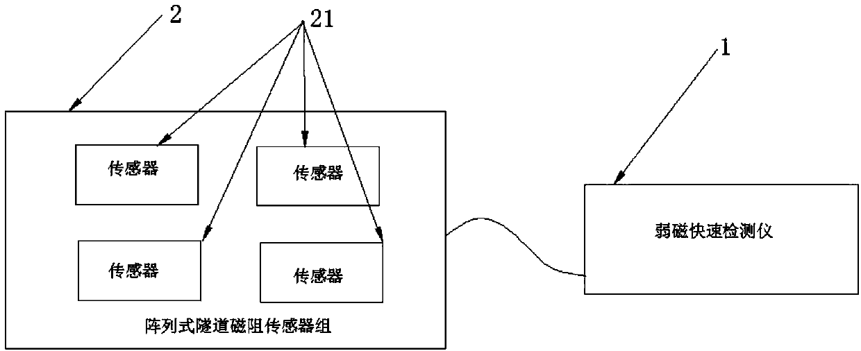
[0025] Such as figure 1 As shown, a detection device for the thickness of a carburized layer includes a connected magnetic field weakening fast detector 1 and an arrayed tunnel magnetoresistive sensor group 2 . Among them, the magnetic field weakening fast detector 1 converts the magnetic induction signal in the welding seam into an electrical signal for analysis and processing, and the array type tunnel magnetoresistive sensor group 2 is used to collect the magnetic induction signal.

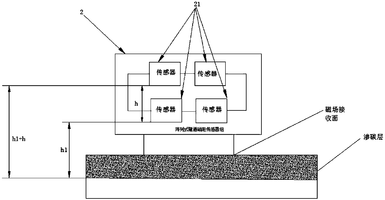
[0026] In a further step, the above-mentioned arrayed tunnel magneto-resistive sensor group 2 includes four sensors 21, and these four sensors 21 are all connected to the above-mentioned weak magnetic fast detector 1, and the four sensors 21 are divided into two rows on average, the first row above the second row.

[0027] During detection, the bottoms of the group of tunnel magnetoresistive sensors 21 are attached parallel to the surface of the workpiece to be detected, that is, the detection...

Embodiment 2

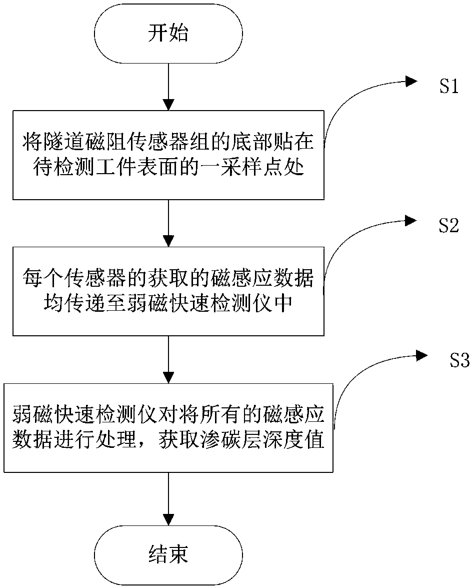
[0030] Such as figure 2 and 3 Shown, a kind of detection method of carburized layer thickness comprises steps:

[0031] S1. Paste the bottom of the group of tunnel magnetoresistive sensors 21 on a sampling point on the surface of the workpiece to be detected;

[0032] S2. The magnetic induction data obtained by each sensor 21 is transmitted to the magnetic field weakening fast detector 1;

[0033] S3. The magnetic field weakening fast detector 1 processes all the magnetic induction data to obtain the carburized layer depth value.

[0034] In the above method, it is necessary to attach the bottom of the tunnel magnetoresistive sensor 21 group to the surface of the workpiece to be detected during detection, and then transmit the magnetic induction data acquired by each sensor 21 to the magnetic field-weakening fast detector 1 in real time. The detector 1 reprocesses all the magnetic induction data to obtain the depth value of the carburized layer.

[0035] It is worth point...


PUM


Abstract

The invention provides a carburized layer thickness detecting device and method. The device includes a weakly magnetic fast detector and array type tunnel magnetoresistive sensor groups, wherein the weakly magnetic fast detector and the array type tunnel magnetoresistive sensor groups are electrically connected with each other, wherein each array type tunnel magnetoresistive sensor group includesfour sensors, and two sensors are located above the other two sensors. The method includes the steps that the bottom of the tunnel magnetoresistive sensor group adheres to the position of a sampling point of the surface of a to-be-detected workpiece; magnetic induction data acquired by all the sensors in each array type tunnel magnetoresistive sensor group is transmitted into the weakly magnetic fast detector; and the weakly magnetic fast detector processes all the magnetic induction data and acquires a carburized layer depth value of the sampling point at the current moment. Through the device and method, the carburized layer thickness of the to-be-detected workpiece can be subjected to quick and efficient nondestructive testing, and an error of the acquired depth value is small.

Description

technical field [0001] The invention relates to the field of carburized layer detection, in particular to a carburized layer thickness detection device and method. Background technique [0002] Carburizing is a kind of metal surface treatment. Carburizing is mostly low-carbon steel or low-alloy steel. The specific method is to place the workpiece into a single-phase austenitic steel with active carburizing medium and heat it to 900--950 degrees Celsius. In the densitic zone, after holding for a sufficient time, the activated carbon atoms decomposed in the carburizing medium will infiltrate into the surface layer of the steel piece, thereby obtaining high carbon content in the surface layer, while the core part still maintains the original composition. This is a common heat treatment process for metal materials. [0003] The material of the carburized workpiece is generally low carbon steel or low carbon alloy steel (the carbon content is less than 0.25%). After carburizing...

Claims


Application Information

Patent Timeline
IPC IPC(8): G01B7/06G01B7/26
CPCG01B7/10G01B7/26
Inventor 于润桥胡博夏桂锁程东方程强强
Owner NINGBO YINZHOU CITAI ELECTRONICS TECH CO LTD
Why Eureka
Try Eureka