Masks and Exposure Equipment

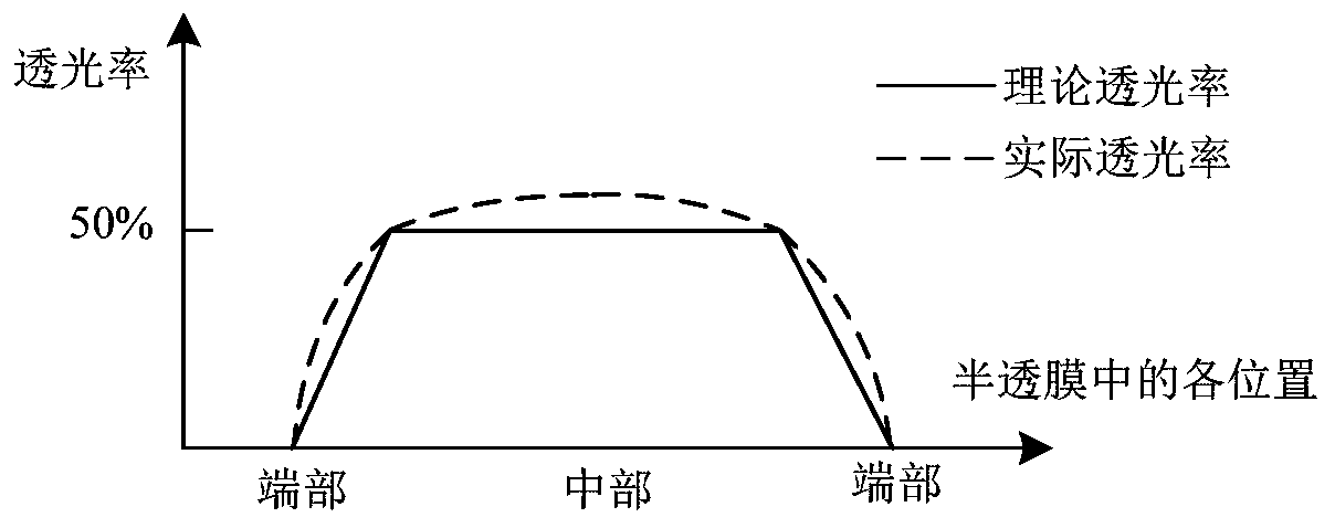
A mask and mask technology, applied in optics, originals for opto-mechanical processing, instruments, etc., can solve the problems of low light transmittance, large light transmittance in semi-transparent area, and large degree of overexposure, etc. To achieve the effect of improving uniformity and uniform exposure

Active Publication Date: 2020-08-07
BOE TECH GRP CO LTD +1
View PDF7 Cites 0 Cited by
  • Summary
  • Abstract
  • Description
  • Claims
  • Application Information

AI Technical Summary

Problems solved by technology

However, during the exposure process, the light source is scanned from one side of the mask to the other side, and smears will occur during scanning, that is, the light has just entered the semi-transparent area from the opaque area and is about to enter the opaque area. When in the semi-transparent area, the light transmittance will have a certain transition, which will lead to a larger actual light transmittance in the semi-transparent area, and a smaller actual light transmittance in the middle.
like figure 1 Shown is a schematic diagram of the light transmittance at each position when the semi-transparent film is used to expose the active region with a large length. The solid line in the figure is the theoretical light transmittance curve, and the dotted line is the actual light transmittance curve. It can be seen that , in the actual exposure, when the actual light transmittance of the semi-transparent film gradually transitions to 50%, it will increase to a certain extent, resulting in overexposure, and the greater the length of the active region, the longer the overexposed area , the degree of overexposure in the middle of the length direction of the active region is greater or even broken, thereby reducing the uniformity of subsequent etching patterning

Method used


Image

  • Masks and Exposure Equipment
  • Masks and Exposure Equipment
  • Masks and Exposure Equipment

Examples


Embodiment Construction

[0040] Specific embodiments of the present invention will be described in detail below in conjunction with the accompanying drawings. It should be understood that the specific embodiments described here are only used to illustrate and explain the present invention, and are not intended to limit the present invention.

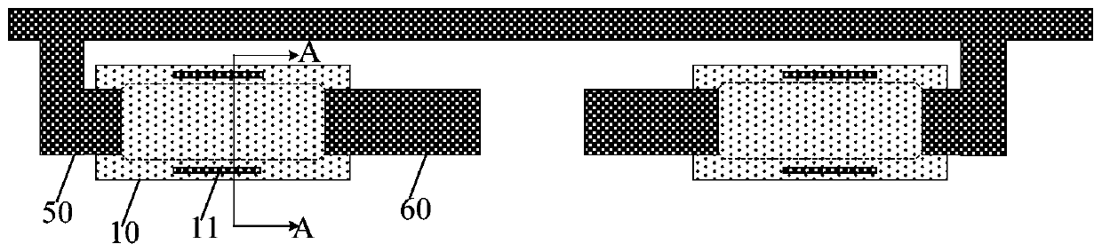
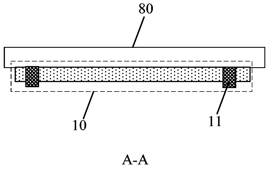
[0041] As an aspect of the present invention, a mask plate is provided for exposing an array substrate, the array substrate includes a display area and a peripheral area surrounding the display area, the display area includes a plurality of display active areas , the peripheral region includes a plurality of peripheral active regions, and the length of the peripheral active regions is greater than the length of the display active region. Specifically, the length of the peripheral active region is greater than 3 μm, usually up to 60 μm; the length of the display active region is less than 3 μm. combine Figure 2 to Figure 8 As shown, the mask plate includes a m...


PUM

PropertyMeasurementUnit
widthaaaaaaaaaa
transmittivityaaaaaaaaaa

Abstract

The invention provides a mask plate. The mask plate is used for exposing an array substrate, the array substrate comprises a display area and a peripheral area encircling the display area, the displayarea comprises a plurality of display active regions, the peripheral area comprises a plurality of peripheral active regions, the length of every peripheral active region is more than the length of every display active region, the mask plate comprises a mask layer, the mask layer comprises a first mask part corresponding to the peripheral active regions, and the first mask part comprises a plurality of mutually spaced mask strips; and in the first mask part, the light transmittance of the mask strips is different from the light transmittance of other parts. The invention also provides an exposure device. The exposure device can improve the exposure uniformity of the active regions of the array substrate.

Description

technical field [0001] The invention relates to the field of manufacturing display devices, in particular to a mask and exposure [0002] equipment. Background technique [0003] In the array substrate, the display area is provided with a plurality of thin film transistors for display, and the non-display area is provided with a plurality of antistatic thin film transistors. Generally, the width of the active layer of the thin film transistor in the display area is generally small to reduce leakage; the width of the active layer of the thin film transistor in the non-display area is large to improve the antistatic effect. During the manufacturing process of the array substrate, in order to reduce the process steps, more and more manufacturers use a half tone mask (Half Tone Mask, HTM) to manufacture the active layer and the source and drain electrodes of the thin film transistor. The half-tone mask plate includes a light-transmitting area, a semi-transparent area and an op...

Claims


Application Information

Patent Timeline
Patent Type & Authority Patents(China)
IPC IPC(8): G03F1/32
CPCG03F1/32
Inventor 徐元杰祁小敬高山
Owner BOE TECH GRP CO LTD
Why Eureka
Try Eureka