Automatic focusing and exposing method

An exposure method and auto-focus technology, applied in the field of exposure machines, can solve the problems of affecting the exposure effect, measurement distance error, exposure error, etc.

Inactive Publication Date: 2021-04-20
ZHONGSHAN AISCENT TECH
View PDF4 Cites 0 Cited by
  • Summary
  • Abstract
  • Description
  • Claims
  • Application Information

AI Technical Summary

Problems solved by technology

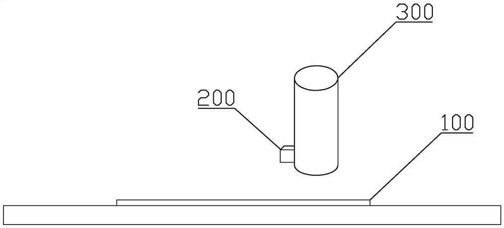
In the actual measurement process, due to the limitations of the existing technology, the distance sensor 200 and the exposure lens 300 are not coaxial, but are installed in front of the exposure direction, resulting in a gap between the distance measured by the distance sensor 200 and the actual exposure distance of the exposure lens 300. There is a certain length of deviation in the exposure direction between
After the distance is measured by the distance sensor 200, the exposure lens 300 will be adjusted immediately, which will result in the situation that the measured distance is not the current exposure distance, and there will be a large error, which will affect the exposure effect
If the error is processed using time-lapse exposure, the time delay is the distance difference between the distance sensor 200 and the exposure lens 300 divided by the moving speed of the exposure lens 300, but due to the influence of the acceleration when the exposure lens 300 starts to move, it cannot Accurately calculate the delay time, it will still cause exposure error
In addition, due to the unevenness of the photoresist plate 100, if there is a sudden bump or sag, the exposure lens 300 will suddenly focus and cause exposure jitter, resulting in partial dark marks.

Method used


Image

  • Automatic focusing and exposing method
  • Automatic focusing and exposing method
  • Automatic focusing and exposing method

Examples


Embodiment Construction

[0018] Embodiments of the present invention are described in detail below, and examples of the embodiments are shown in the drawings, wherein the same or similar reference numerals denote the same or similar elements or elements having the same or similar functions throughout. The embodiments described below by referring to the figures are exemplary only for explaining the present invention and should not be construed as limiting the present invention.

[0019] In the description of the present invention, it should be understood that the orientation descriptions, such as up, down, front, back, left, right, etc. indicated orientations or positional relationships are based on the orientations or positional relationships shown in the drawings, and are only In order to facilitate the description of the present invention and simplify the description, it does not indicate or imply that the device or element referred to must have a specific orientation, be constructed and operated in ...


PUM


Abstract

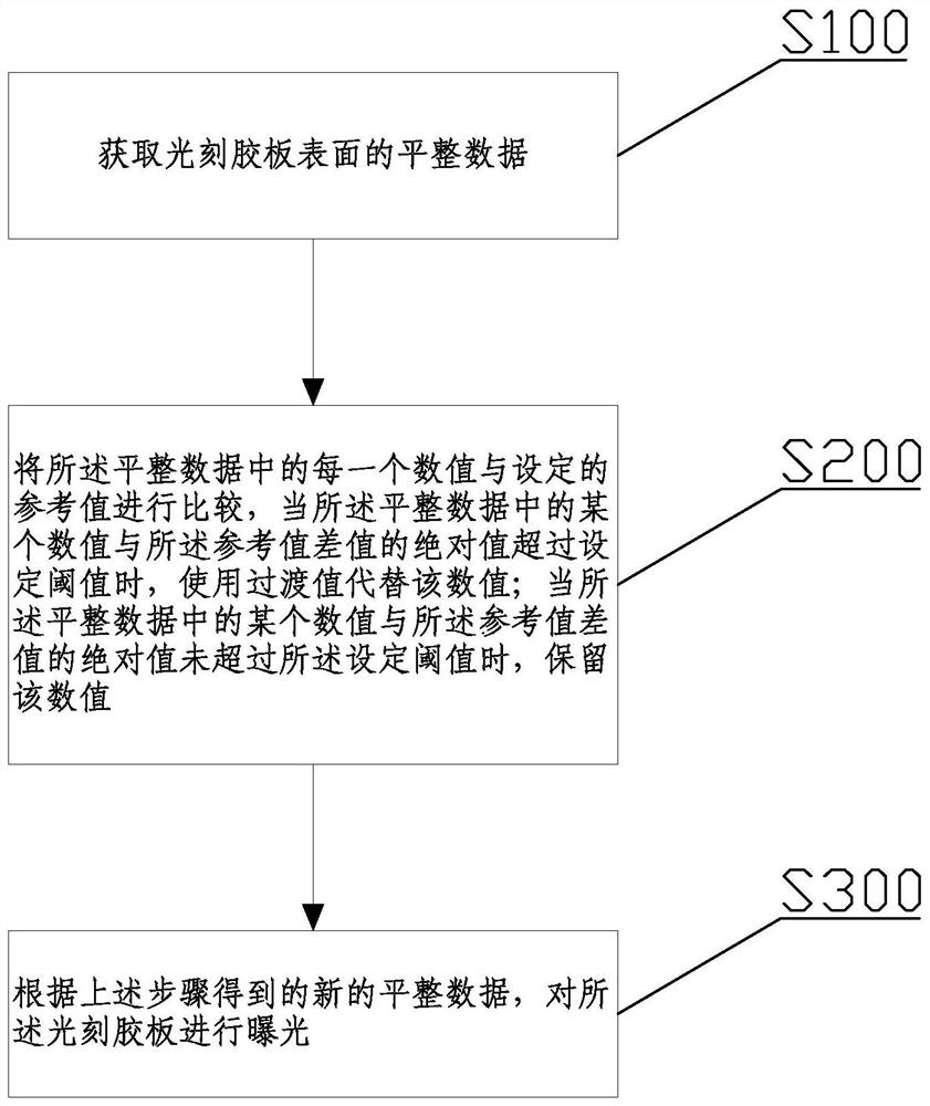
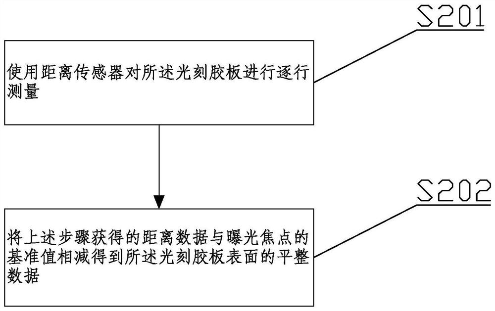
The invention discloses an automatic focusing and exposing method. The method comprises the following steps: acquiring flatness data of the surface of a photoresist plate; comparing each numerical value in the flatness data with a set reference value, and when the absolute value of a difference between a certain numerical value in the flatness data and the reference value exceeds a set threshold value and replacing the numerical value with a transition value, or when the absolute value of the difference value between a certain numerical value in the flatness data and the reference value does not exceed the set threshold value, reserving the numerical value; and exposing the photoresist plate according to the new flatness data obtained in the previous step. According to the method, the overall exposure effect of an exposure machine can be improved, exposure is more uniform, dark marks cannot be generated, and therefore, the yield of exposure conducted through the photoresist plate is increased.

Description

technical field [0001] The invention relates to the technical field of exposure machines, in particular to an automatic focus exposure method. Background technique [0002] Exposure is to use a light source of a certain wavelength to partially irradiate the photoresist plate 100, and the photoresist in the irradiated part will undergo chemical changes, while the properties of the photoresist that has not been irradiated remain unchanged, so that the exposed photoresist can be exposed in the subsequent process. and non-exposed regions to obtain a specific shape. In order to completely and accurately reproduce the shape on the photoresist, it is necessary to ensure that the entire photoresist is within the focus range regardless of the top layer part or the part close to the substrate surface. [0003] In traditional autofocus exposure methods, such as image 3 As shown, the distance between the photoresist plate 100 and the distance sensor 200 is used for testing, and the fo...

Claims


Application Information

Patent Timeline
Patent Type & Authority Applications(China)
IPC IPC(8): G03F7/20
Inventor 潘浩源
Owner ZHONGSHAN AISCENT TECH
Why Eureka
Try Eureka