
A single-image shadow removal method based on adaptive light transfer based on block matching

A shadow removal and adaptive technology, applied in image enhancement, image analysis, instruments, etc., can solve problems such as reflectivity changes, loss of texture details, algorithm failures, etc., to achieve natural shadow removal results, consistent lighting conditions, The effect of protecting texture information

Inactive Publication Date: 2020-07-10
TIANJIN UNIV
View PDF5 Cites 0 Cited by
  • Summary
  • Abstract
  • Description
  • Claims
  • Application Information

AI Technical Summary

Problems solved by technology

This method can remove inhomogeneous shadows, however, smooth thin-plate approximation is difficult to accurately estimate the shadow scale factor in textured and highly structured images; moreover, the algorithm fails when shadowed regions contain multiple texture types
Guo et al. calculated the ratio of direct light and ambient light, and obtained the shadow removal image by re-illuminating each pixel, but this method did not take into account the change of reflectivity, which easily caused the loss of texture details.
Khan et al. obtained a Bayesian formula by integrating multi-level color conversion, and used it for shadow removal. By optimizing the cost function, a better shadow removal effect can be obtained; however, due to the use of multi-level color conversion, uneven or curved Surface shadow removal, the effect is often not ideal

Method used


Image

  • A single-image shadow removal method based on adaptive light transfer based on block matching
  • A single-image shadow removal method based on adaptive light transfer based on block matching
  • A single-image shadow removal method based on adaptive light transfer based on block matching

Examples


Embodiment 1

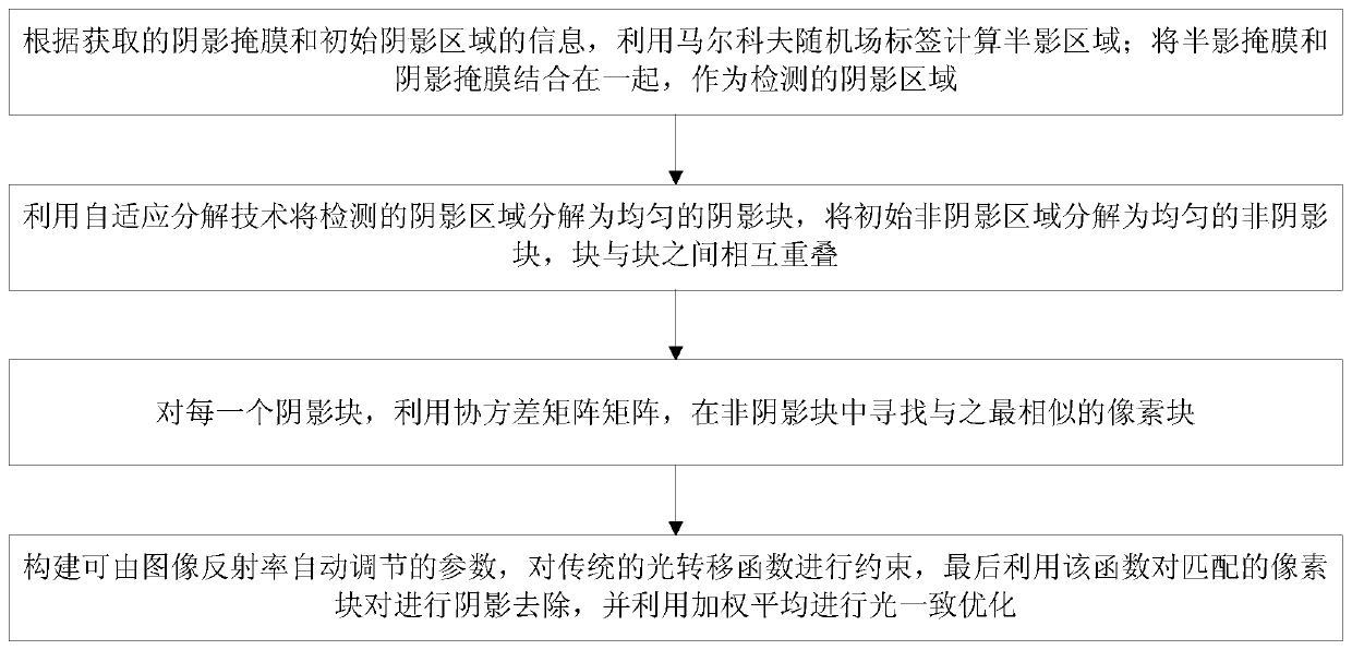
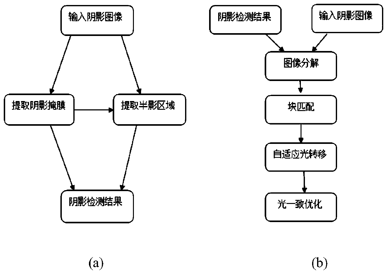
[0044] A single-frame shadow removal method based on block matching for adaptive light transfer, see figure 1 and figure 2 , the method includes the following steps:

[0045] 101: Provide the pixel coordinates of the initial seed point by the user in the initial shadow area and the initial non-shadow area by clicking the mouse, and use the RGB value in the coordinate field to perform support vector training, and divide the image pixels into shadow pixels and non-shadow pixels;

[0046] 102: Based on the pixel coordinates of the initial seed point, iterative region growth is performed, and shadow pixels are added to the initial shadow region to form a shadow mask;

[0047] 103: According to the acquired shadow mask and information of the initial shadow area, calculate the penumbra area by using the Markov random field label; combine the penumbra mask and the shadow mask together as the detected shadow area;

[0048] 104: Decompose the detected shadow area into uniform shadow...

Embodiment 2

[0053] The following is combined with specific calculation formulas, examples, figure 1 and figure 2 , the scheme in embodiment 1 is further introduced, see the following description for details:

[0054] 201: shadow detection;

[0055] Shadow detection is the premise of shadow removal, and the quality of the detection effect directly affects the subsequent shadow removal effect. The embodiment of the present invention detects the shadow area based on a user-assisted method. The user clicks the mouse in the initial shadow area and the non-shade area to provide the initial seed point coordinates, and uses the RGB values ​​​​in the coordinate field to perform support vector training and divide the image pixels. into shaded pixels and non-shaded pixels. Based on the initial seed point coordinates provided by the user, iterative region growing is performed to add shadow pixels to the initial shadow region to form a shadow mask.

[0056] see figure 2 (a), According to the ac...

Embodiment 3

[0115] Combined with the specific experimental data, Figure 3-Figure 7 Validation and robustness of the scheme in Examples 1 and 2 are verified, see the following description for details:

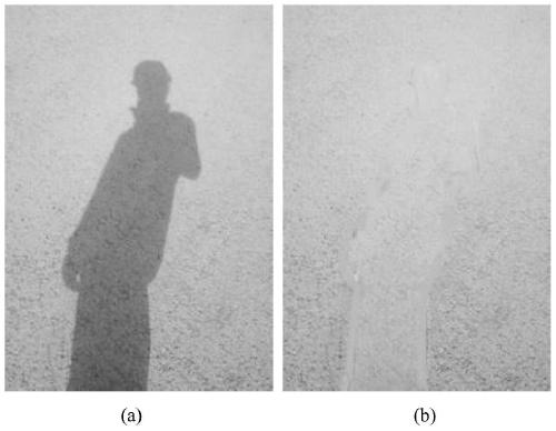
[0116] image 3 To deal with unevenly shaded images, image 3 There are obvious changes in the brightness of the shaded areas in (a), with darker areas at the bottom of the image. The embodiment of the present invention fully considers the brightness information at different positions by performing adaptive light transfer for each shadow block independently, which helps to remove uneven shadows, such as image 3 After the shadow is removed in (b), the illumination is consistent.

[0117] Figure 4 For handling shaded images containing highly structured textures, Figure 4 The image in (a) has a bumpy structure. The embodiment of the present invention improves the traditional light transfer function by using an adaptive parameter, which can be adjusted automatically with the reflectiv...


PUM


Abstract

An adaptive light transfer single shadow removal method based on block matching, including the following steps: using Markov random field labels to calculate the penumbra area based on the acquired shadow mask and initial shadow area information; converting the penumbra mask into Combined with the shadow mask, it is used as the detected shadow area; adaptive decomposition technology is used to decompose the detected shadow area into uniform shadow blocks, and the initial non-shadow area is decomposed into uniform non-shadow blocks, and the blocks are mutually Overlap; for each shadow block, use the covariance matrix matrix to find the most similar pixel block in the non-shadow block; construct parameters that can be automatically adjusted by the image reflectance to constrain the traditional light transfer function, and finally use this The function performs shadow removal on matched pairs of pixel blocks and uses weighted averaging for light-consistent optimization. The present invention can achieve high-quality shadow removal effects on uneven shadows, shadows on curved surfaces, and multi-texture type shadows.

Description

technical field [0001] The invention relates to the field of computer image processing, in particular to a block-matching-based adaptive light transfer single-frame shadow removal method, which can be used for target extraction, film and television special effect production, and the like. Background technique [0002] The purpose of image shadow removal is to restore normal lighting conditions in shadowed areas, so that shadow removal results are consistent with the texture and lighting of the surrounding environment. As a research hotspot in the field of computer graphics and computer vision, image shadow removal technology has important research value in object recognition, scene analysis, 3D reconstruction and so on. [0003] The existence of shadows will seriously affect the quality of computer images, interfere with image information extraction and judgment, and removing shadows in images will help improve the performance of computer vision. To solve this problem, dome...

Claims


Application Information

Patent Timeline
Patent Type & Authority Patents(China)
IPC IPC(8): G06T5/00G06T7/11G06T7/136
CPCG06T7/11G06T7/136G06T2207/20081G06T2207/10004G06T5/94
Inventor 何凯甄蕊黄婉蓉沈成南
Owner TIANJIN UNIV
Learn More