Monitoring system and video transmission method

A monitoring system and video information technology, applied in signal transmission systems, closed-circuit television systems, digital video signal modification, etc., can solve the problems of not being able to see a clear code stream, unable to transmit camera images to the monitoring center, and not suitable for wiring, etc. , to achieve the effect of increasing storage

Pending Publication Date: 2018-03-16
BEIJING ZHIGUANG BOYUAN SCI & TECH
View PDF0 Cites 0 Cited by
  • Summary
  • Abstract
  • Description
  • Claims
  • Application Information

AI Technical Summary

Problems solved by technology

Due to the limitation of front-end bandwidth, the current monitoring system can only transmit streaming media with low bit rate
Cause the backend can not watch the clear code stream
At the same time, for the monitoring of remote mountainous areas, due to the dangerous terrai

Method used


Image

  • Monitoring system and video transmission method
  • Monitoring system and video transmission method
  • Monitoring system and video transmission method

Examples


Example

[0040] First embodiment

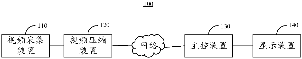
[0041] The embodiment of the present invention provides a monitoring system 100, which is used to collect and transmit on-site video information to the display device 140 where the user is located, so that the user can grasp the situation of the site in real time. See figure 1 , Is a block diagram of the circuit structure of the monitoring system 100 provided by an embodiment of the present invention. The monitoring system 100 includes a video capture device 110, a main control device 130, a display device 140, and a video compression device 120. The video capture device 110 is electrically connected to the video compression device 120. The video compression device 120, the main control device 130, and the display device 140 are in turn connection.

[0042] Wherein, the video acquisition device 110 is electrically connected to the video compression device 120, and is used to collect the first video information of the monitoring site and transmit the first...

Example

[0083] Second embodiment

[0084] See Figure 5 , Figure 5 This is a flowchart of a video transmission method provided by a preferred embodiment of the present invention. It should be noted that the basic principles and technical effects of the video transmission method provided in this embodiment are the same as those in the above embodiments. For a brief description, for the parts not mentioned in this embodiment, please refer to the above embodiments. Corresponding content. The video transmission method includes:

[0085] Step S501: Use a video acquisition device 130 to collect the first video information of the surveillance site, and transmit the first video information to a video compression module.

[0086] Step S502: Use a video compression device 120 to compress and encode the first video information to generate second video information.

[0087] Step S503: Use a video compression device 120 to transmit the second video information to a main control device 130.

[0088] In...


PUM


Abstract

Embodiments of the present invention provide a monitoring system and a video transmission method, which relate to the technical field of video collection and transmission. The system includes a video capture device, a main control device, a display device and a video compression device, the video capture device is electrically connected to the video compression device, and the video compression device, the main control device, and the display device are connected in sequence, wherein the video compression device is used for video compression. The first video information collected and transmitted by the acquisition device is compressed and encoded to generate the second video information, and the second video information is transmitted to the main control device. Since the code stream of the first video information processed by the video compression device becomes smaller , thereby increasing the storage space of the storage device in disguise; in addition, since the video compression device and the video acquisition device are physically connected, there is no limit to the bandwidth of the first video information, and the clarity of the first video information will not be affected during the decoding process. The degree of damage is caused, and thus the high-definition first video information can be displayed through the display device in time.

Description

technical field [0001] The invention relates to the technical field of video collection and transmission, in particular to a monitoring system and a video transmission method. Background technique [0002] The monitoring system is composed of five major parts: camera, transmission, control, display, record and registration. The camera transmits or Ethernet video images to the control host through the coaxial video cable, and the control host then distributes the video signal to each monitor and recording device, and simultaneously records the voice signal to be transmitted into the video recorder. By controlling the host, the operator can issue instructions to control the up, down, left, and right movements of the pan / tilt, and perform zoom and zoom operations on the lens. switch between. Using the special video processing mode, you can record, playback, process and other operations on the image to achieve the best video effect. [0003] With the continuous development of...

Claims


Application Information

Patent Timeline
IPC IPC(8): H04N7/18H04N19/42H04N19/85G08C17/02H04N21/4402
CPCH04N7/18H04N19/42H04N19/85H04N21/4402G08C17/02
Inventor 马兆远雷悦钦
Owner BEIJING ZHIGUANG BOYUAN SCI & TECH
Why Eureka
Try Eureka