Method for automatically determining puncture point position

A technology for automatically determining and puncturing points, applied in the medical field, can solve problems such as unreasonable puncture point positions and failure to find target blood vessels, and achieve the effect of avoiding unreasonable positions

Inactive Publication Date: 2018-03-20
BEIJING TECHNOLOGY AND BUSINESS UNIVERSITY
View PDF0 Cites 15 Cited by
  • Summary
  • Abstract
  • Description
  • Claims
  • Application Information

AI Technical Summary

Problems solved by technology

[0006] In order to solve the problem in the prior art that the position of the selected puncture point may be unreasonable or the target blood vessel cannot be found when the condition of the blood vessel is not good, the embodiment of the present invention provides a method for automatically determining the position of the puncture point

Method used


Image

  • Method for automatically determining puncture point position
  • Method for automatically determining puncture point position
  • Method for automatically determining puncture point position

Examples


Embodiment 1

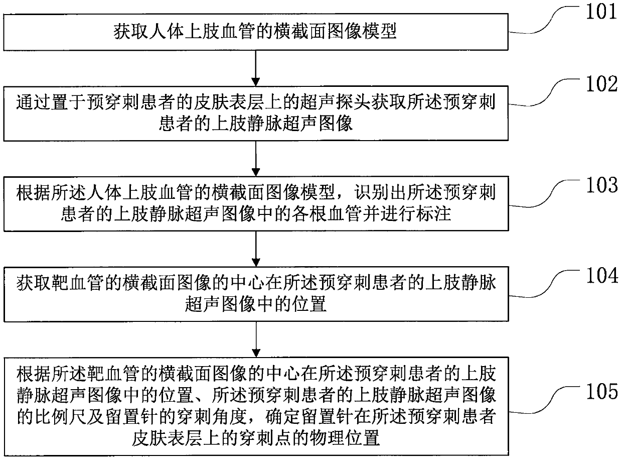
[0041] Such as figure 1 As shown, the embodiment of the present invention provides a method for automatically determining the position of the puncture point, and the method includes the following steps:

[0042] In step 101, a cross-sectional image model of a human upper limb blood vessel is acquired.

[0043] In the embodiment of the present invention, a large number of ultrasonic images of human upper limb veins marked with blood vessel information are trained by Faster RCNN algorithm to obtain a cross-sectional image model of human upper limb.

[0044] In step 102, an ultrasound image of upper limb veins of the pre-puncture patient is acquired through an ultrasound probe placed on the skin surface of the pre-puncture patient.

[0045] In the embodiment of the present invention, medical personnel place an ultrasonic probe on the skin surface of the pre-puncture patient to obtain an ultrasound image of the upper limb vein of the pre-puncture patient, wherein the ultrasound i...

Embodiment 2

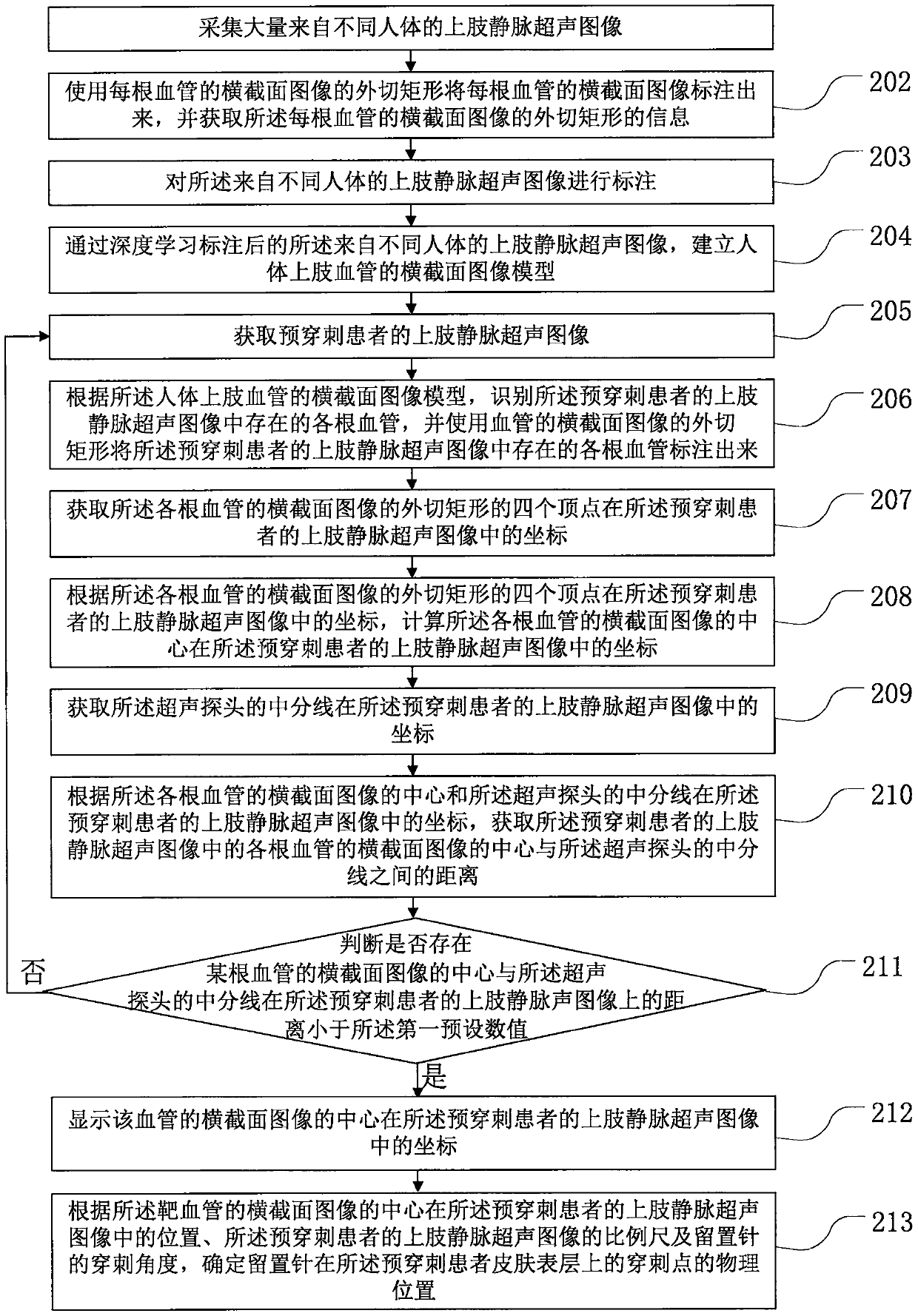
[0054] Such as figure 2 As shown, in the embodiment of the present invention, the embodiment of the present invention provides a method for automatically determining the position of the puncture point, and the method includes the following steps:

[0055] In step 201, a large number of ultrasound images of upper limb veins from different human bodies are collected.

[0056] In the embodiment of the present invention, a large number of ultrasound images of upper limb veins from different human bodies are collected in advance through an ultrasound probe with an image acquisition card, and each ultrasound image of upper limb veins includes a cross-sectional image of at least one blood vessel, wherein each The upper extremity venous ultrasound images have the same size, 230×300 pixels, and can be the original image collected by the ultrasound probe, or an image intercepted from the original image.

[0057] In step 202, if image 3 As shown, the circumscribed rectangle 3 of the ...


PUM


Abstract

The invention discloses a method for automatically determining the position of a puncture point, which belongs to the field of medical technology. According to the cross-sectional image model of human upper limb blood vessels, the present invention identifies and marks each blood vessel in the upper limb vein ultrasound image of the pre-puncture patient, and obtains the cross-sectional image of the target blood vessel. The position of the center in the upper extremity venous ultrasound image of the pre-puncture patient, according to the position of the center of the cross-sectional image of the target vessel in the upper extremity venous ultrasound image of the pre-puncture patient, the scale of the upper limb venous ultrasound image of the pre-puncture patient, and the size of the indwelling needle Puncture angle, to obtain the physical position of the puncture point of the indwelling needle on the skin surface of the pre-punctured patient, without the need to determine the position of the puncture point on the patient's skin surface through the nurse's eyes and hands, thereby avoiding the existence of the puncture point selected during puncture The position is unreasonable or the target vessel cannot be found.

Description

technical field [0001] The invention relates to the field of medical technology, in particular to a method for automatically determining the position of a puncture point. Background technique [0002] The venous indwelling needle is a device designed in clinical medicine to alleviate the pain caused by repeated needle sticking. It is inserted into the vein of the patient with a cannula through the puncture needle, and then the puncture needle is pulled out, leaving the cannula in the patient's body. The connector located outside the patient's body connected with the cannula is connected to the intravenous injection device for intravenous injection of the patient, or connected to the blood collection device for blood collection from the patient's body. [0003] At present, when a patient is punctured with an intravenous indwelling needle, the target blood vessel on the patient's body and the position of the puncture point on the target blood vessel are determined by the nurse...

Claims


Application Information

Patent Timeline
Patent Type & Authority Applications(China)
IPC IPC(8): A61M5/42A61B5/153
CPCA61M5/427A61B5/150748A61B5/153
Inventor 郭克友贾海晶
Owner BEIJING TECHNOLOGY AND BUSINESS UNIVERSITY
Why Eureka
Try Eureka