
Steam turbine-generator safety protection system and method used in large power plants

A safety protection and generator technology, applied in safety devices, engine components, machines/engines, etc., can solve the problems of overspeed of steam turbines, lack of overspeed of steam turbines, etc., to avoid overspeed, reduce initial impact strength, and improve the effect of automation

Active Publication Date: 2022-03-25
中国能源建设集团华中电力试验研究院有限公司
View PDF0 Cites 0 Cited by
  • Summary
  • Abstract
  • Description
  • Claims
  • Application Information

AI Technical Summary

Problems solved by technology

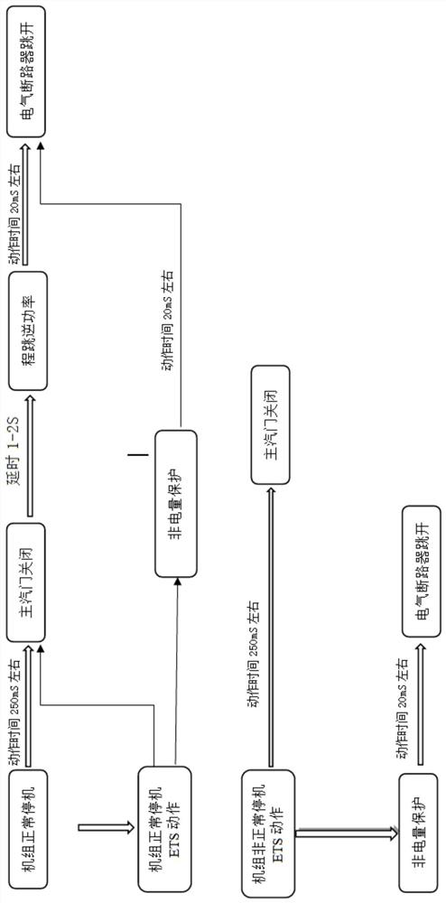
In the case of this configuration, regardless of whether it is an emergency shutdown or a normal shutdown, the thermal protection (due to the shutdown action due to the brake) will act before the tripping and reverse power protection, which may cause the main steam valve of the turbine to fail. In the case that the group grid connection switch has been tripped, there is a risk of overspeeding of the steam turbine
[0004] In the event of a fault, the ETS cabinet simultaneously sends a trip command to the main steam valve and the protection C cabinet (non-electricity cabinet) of the generator-transformer group; the time for the valve to be fully closed is about 250-350mS, and the time for the circuit breaker to be disconnected is about 20-42mS , the time difference is about 232-310mS, which can easily lead to overspeeding of the steam turbine under different conditions
At present, there is a lack of a system and method that can avoid overspeeding of steam turbines

Method used


Image

  • Steam turbine-generator safety protection system and method used in large power plants
  • Steam turbine-generator safety protection system and method used in large power plants
  • Steam turbine-generator safety protection system and method used in large power plants

Examples


Embodiment Construction

[0038] In order to describe the technical content, achieved goals and effects of the present invention in detail, the following descriptions will be made in conjunction with the embodiments and accompanying drawings.

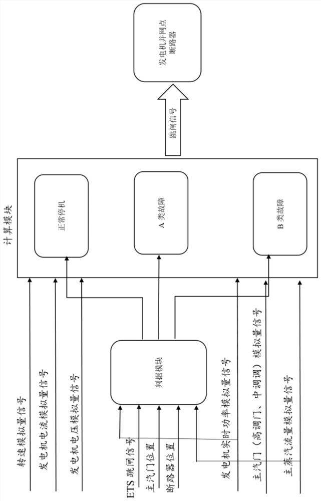
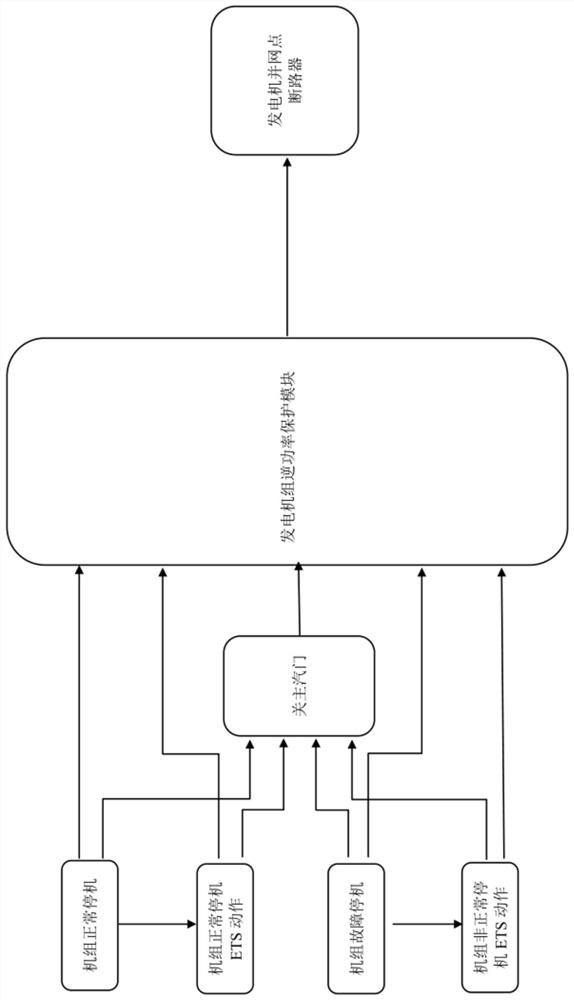
[0039] like figure 2 As shown, a steam turbine-generator safety protection applied in a large power plant includes a signal acquisition terminal, a criterion module, a calculation module and a generator grid-connected circuit breaker. The signal acquisition terminal is used to collect ETS trip signals, main steam valve Closing signal, circuit breaker trip position signal and analog quantity acquisition data; the signal acquisition end inputs the ETS trip signal, main steam valve closing signal, circuit breaker trip position signal Flow analog signal, generator real-time power analog signal, speed analog signal, generator current analog signal, generator voltage analog signal and main steam valve analog signal are input to the calculation module, and the criteri...


PUM


Abstract

The invention discloses a steam turbine-generator safety protection system applied to a large-scale power plant, including a signal acquisition terminal, a criterion module, a calculation module and a generator grid-connected circuit breaker, and also discloses a safety protection system applied to a large-scale power plant The steam turbine-generator safety protection method comprises the following steps of inputting the ETS trip signal, the main steam valve closing signal, and the circuit breaker trip position signal into the criterion module, and the criterion module judges the state type according to the received signal; collects the state type data and the analog quantity The data is input into the calculation module; the calculation module judges the follow-up action according to different state type data and real-time operation data. The criterion module judges the state type through the ETS trip signal, the main steam valve closing signal, and the circuit breaker trip position signal, and the calculation module judges the follow-up action according to the implementation operation data and state type data, so that the steam turbine-generator can achieve redundant release energy and output power grid energy Open the generator circuit breaker after balancing to avoid overspeeding of the generator.

Description

technical field [0001] The invention relates to the field of safety protection of steam turbine-generator equipment in large-scale power plants, in particular to a system and method for safety protection of steam turbine-generators applied in large-scale power plants. Background technique [0002] At present, large-scale power plants of 660MW generally have large turbine vibrations or failures in the oil system of the turbine body under high load conditions (60% and above), resulting in varying degrees of overspeeding of steam turbines after ETS action. There is also the overspeed phenomenon in emergency manual brake shutdown. [0003] After research, such as figure 1 As shown, it is found that in the power trip protection of electromechanical interlocking of the power plant, two protections, "thermal protection" and "reversal power" are set for the electric protection of the turbine tripping. The former is protection tripping, and the latter is normal shutdown. trip. The...

Claims


Application Information

Patent Timeline
Patent Type & Authority Patents(China)
IPC IPC(8): F01D21/00F01D15/10
CPCF01D21/00F01D15/10
Inventor 刘卓张国瑞龙岩禹波陈诚
Owner 中国能源建设集团华中电力试验研究院有限公司
Learn More