
Thick plate ultra-narrow gap laser wire-filling welding device and method

A technology of laser wire filling and welding method, which is applied in the direction of laser welding equipment, welding equipment, metal processing equipment, etc., can solve the problems of low welding efficiency, multi-layer number, slow speed, etc., and achieve improved welding stability and good scalability Thickness, the effect of improving welding efficiency

Active Publication Date: 2018-03-20
HUAZHONG UNIV OF SCI & TECH
View PDF5 Cites 19 Cited by
  • Summary
  • Abstract
  • Description
  • Claims
  • Application Information

AI Technical Summary

Problems solved by technology

Existing ultra-narrow-gap laser welding methods for thick plates generally include ultra-narrow-gap laser arc welding and ultra-narrow-gap laser wire-filled welding. These two welding methods have their own advantages and disadvantages: If the distance is small, the arc is easily attracted by the side wall, which makes it difficult to control the stability of the welding process; while in laser filler wire welding, because the laser needs to melt the base metal and welding wire, the penetration depth is very shallow, and it often needs more welding when welding thick plates. Slow speed and more layers, low welding efficiency
The Chinese patent with the publication number CN102059452A is essentially pure laser wire-fill welding. The three beams are arranged in a specific form, but they are all used to melt the welding wire, which cannot overcome the problems of shallow penetration and low efficiency of laser wire-fill welding.

Method used

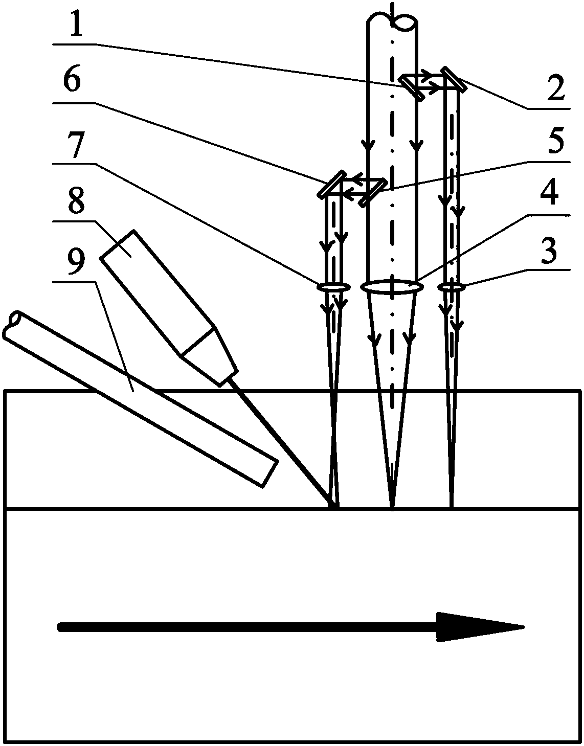

Image

  • Thick plate ultra-narrow gap laser wire-filling welding device and method
  • Thick plate ultra-narrow gap laser wire-filling welding device and method
  • Thick plate ultra-narrow gap laser wire-filling welding device and method

Examples


Embodiment Construction

[0025] The following will clearly and completely describe the technical solutions in the embodiments of the present invention with reference to the accompanying drawings in the embodiments of the present invention. Obviously, the described embodiments are only some, not all, embodiments of the present invention. Based on the embodiments of the present invention, all other embodiments obtained by persons of ordinary skill in the art without making creative efforts belong to the protection scope of the present invention.

[0026] The purpose of the present invention is to provide a thick plate ultra-narrow gap laser wire-filled welding device and method to solve the problems in the prior art, so that the welding efficiency of thick plate ultra-narrow gap laser wire-filled welding can be improved, and at the same time, it can be effectively cleaned. Deep and narrow bevel to ensure joint quality.

[0027] In order to make the above objects, features and advantages of the present i...


PUM

PropertyMeasurementUnit
thicknessaaaaaaaaaa

Abstract

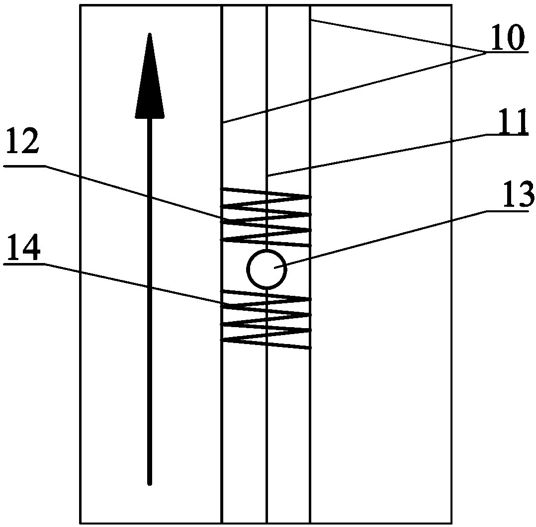
The invention discloses a thick plate ultra-narrow gap laser wire-filling welding method. Main light beams are divided into a cleaning light beam, a deep penetration light beam and a wire-filling light beam. A laser cleaning technology is applied to cleaning of a thick plate ultra-narrow gap groove and compounded with a laser deep penetration wire-filling welding technology, and the problem that it is difficult to effectively clean the deep and narrow groove by means of an existing method is solved. The laser deep penetration welding and the laser wire-filling welding are effectively combined,and the thick plate ultra-narrow gap laser wire-filling welding method has the advantages of a large penetration depth, good bridging ability and expandable thickness and the like. Welding stabilityis improved, laser cleaning and laser welding are performed simultaneously, welding quality can be greatly improved, and the connector quality is guaranteed. The invention further provides a welding device adopting the method, the laser cleaning and the laser welding are performed simultaneously, and welding efficiency is improved.

Description

technical field [0001] The invention relates to the technical field of thick plate narrow gap welding, in particular to a thick plate ultra-narrow gap laser wire-filled welding device and method. Background technique [0002] Thick plate welding is a key technology in the manufacturing process of large-scale equipment such as ships, oceans, rail transit, pressure vessels and bridge construction. The proposal of the thick plate ultra-narrow gap welding method effectively reduces the groove filling area and the number of welding layers, greatly reduces the welding heat input, welding deformation and residual stress, and improves the welding efficiency and joint quality. However, due to the limited penetration of arc welding, multi-layer welding is still required to realize the connection and forming of thick plates. Laser welding has the advantages of high energy density, large penetration depth, and fast welding speed, but pure laser self-fluxing welding has disadvantages su...

Claims


Application Information

Patent Timeline
Patent Type & Authority Applications(China)
IPC IPC(8): B23K26/26B23K26/064B23K26/067
CPCB23K26/064B23K26/0676B23K26/26
Inventor 王春明张熊米高阳蒋平邵新宇
Owner HUAZHONG UNIV OF SCI & TECH
Learn More