
Cutting method of cutting ultrasonic auxiliary lines and apparatus thereof, and a method of producing wafers

A technology of cutting device and cutting method, which is applied to fine working devices, manufacturing tools, stone processing equipment, etc., can solve the problems of cutting energy loss of cutting wire mesh 15, jumper wire and disconnection of cutting wire mesh 15, etc.

Inactive Publication Date: 2018-03-20
AUO CRYSTAL
View PDF9 Cites 2 Cited by
  • Summary
  • Abstract
  • Description
  • Claims
  • Application Information

AI Technical Summary

Problems solved by technology

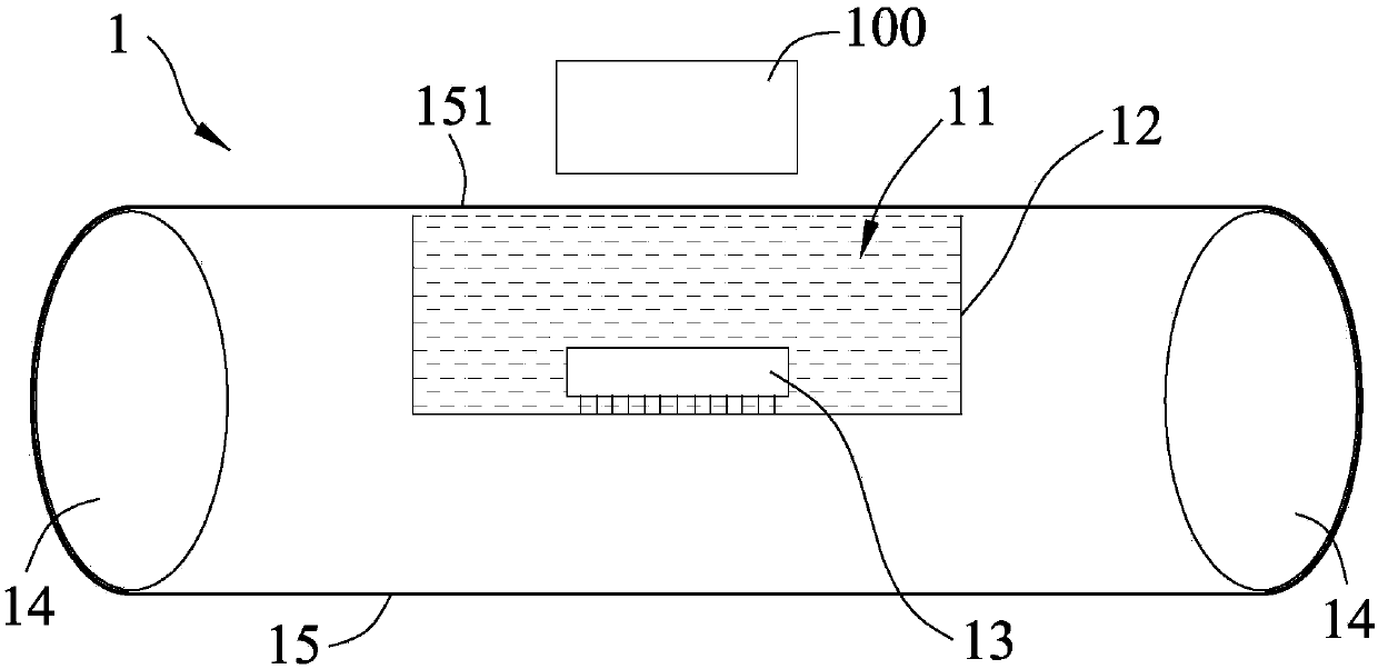
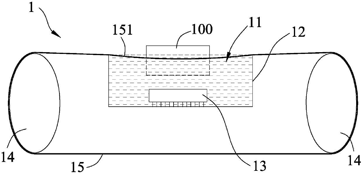
[0004] However, when the ultrasonic wire cutting device 1 of the previous proposal is combined with its ultrasonic wire cutting method for cutting, it is necessary to immerse the crystalline silicon ingot 100 to be cut and the cutting side 151 of the cutting wire mesh 15 into the cutting liquid (suspension Mortar) 11, and cutting in the cutting fluid (suspension mortar) 11, which will cause the loss of cutting energy of the cutting wire network 15, in addition, because the cutting process must have the crystalline silicon ingot 100 and the The cutting wire net 15 is immersed in the cutting fluid 11, which may easily cause jumping and disconnection of the cutting wire net 15.

Method used


Image

  • Cutting method of cutting ultrasonic auxiliary lines and apparatus thereof, and a method of producing wafers
  • Cutting method of cutting ultrasonic auxiliary lines and apparatus thereof, and a method of producing wafers
  • Cutting method of cutting ultrasonic auxiliary lines and apparatus thereof, and a method of producing wafers

Examples


Embodiment Construction

[0047] The present invention will be described in detail below in conjunction with the accompanying drawings and embodiments.

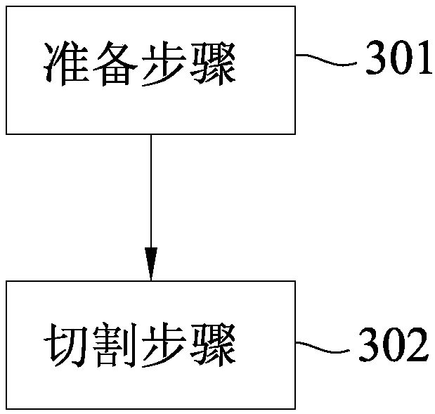
[0048] refer to image 3 , an embodiment of the ultrasonic-assisted wire cutting method of the present invention includes a preparation step 301 and a cutting step 302 .

[0049] Cooperate with reference Figure 4 , first perform the preparation step 301 , prepare an ultrasonic assisted wire cutting device 2 , and inject a cutting fluid 200 into the ultrasonic assisted wire cutting device 2 .

[0050] Specifically, refer to Figure 5 , Figure 5 display edge Figure 4 A section view obtained by a secant line V-V. The ultrasonic auxiliary wire cutting device 2 includes a base body 20, an ultrasonic oscillator 3 arranged on the base body 20, two control devices 5 arranged on opposite sides of the base body 20, and a plurality of control devices 5 corresponding to the control device 5. The cutting line 4 is connected so as to be located on the base...


PUM

PropertyMeasurementUnit
widthaaaaaaaaaa

Abstract

A sawing method of cutting ultrasonic auxiliary lines includes a preparation step and a cutting step. The preparation step includes: providing an ultrasonic auxiliary line cutting apparatus and a to-be-cut object, wherein the ultrasonic auxiliary line cutting apparatus includes a tank defining a receiving space having an opening, an ultrasonic vibrator disposed in the tank, a cutting liquid arranged in the receiving space, and multiple cutting lines located above the opening and spaced apart from the cutting liquid. The cutting step includes moving the to-be-cut object towards the direction ofthe cutting lines so that the to-be-cut object is cut by the cutting lines to form multiple cut grooves and is immerged into the cutting liquid, each of the cut grooves having a radial width generating capillary action and allowing the cutting liquid to enter the cut grooves by the capillary action. Therefore, ultrasonic energy can be simultaneously conducted to the to-be-cut object and the cutting lines to avoid line jumping or breaking of the cutting lines and reduce the energy loss. The invention also provides an ultrasonic auxiliary line cutting apparatus for executing the method and a method of producing wafers.

Description

technical field [0001] The invention relates to a cutting method and its device, in particular to an ultrasonic-assisted wire cutting method and its device, and a chip manufacturing method. Background technique [0002] China Patent Publication No. 103085179A (hereinafter referred to as the previous case) discloses an ultrasonic wire cutting method and special equipment. refer to figure 1 An ultrasonic wire cutting device 1 of the previous case includes a solution tank 12 that can accommodate cutting liquid (suspension mortar) 11, an ultrasonic vibrating plate 13 arranged in the solution tank 12, and two opposite sides of the solution tank 12. The guide wheel 14 on the side, and a plurality of cutting wire nets 15 surrounding the guide wheel 14 and having a cutting side 151 on the solution tank 12, a crystalline silicon ingot 100 to be cut is placed on the cutting side 151 . [0003] refer to figure 2 , make the cutting wire net 15 do reciprocating cutting motion, and m...

Claims


Application Information

Patent Timeline
Patent Type & Authority Applications(China)
IPC IPC(8): B28D5/04
CPCB28D5/045B28D5/0076B28D5/047
Inventor 黄农晏詹志鸿陈政羡
Owner AUO CRYSTAL
Learn More