Airport baggage conveying device

A technology for handling device and luggage, which is applied to conveyor control device, transportation and packaging, conveyors, etc., can solve the problems of unsuitable handling of checked luggage in large-flow airports, inability to ensure the stability of luggage, and complex structure of the transportation system. The effect of avoiding personal safety problems, improving space utilization, and promoting development

Pending Publication Date: 2018-03-20
SOUTHWEST JIAOTONG UNIV
View PDF10 Cites 2 Cited by
  • Summary
  • Abstract
  • Description
  • Claims
  • Application Information

AI Technical Summary

Problems solved by technology

[0003] According to the search, the technology of related intelligent handling devices has appeared at present, such as the "multifunctional luggage checking device" disclosed in Chinese patent application number 201410799500.6. This device has a simple structure and can only transport one suitcase at a time, which is inefficient.
Another example is the Chinese Patent Application No. 200610141658.X which discloses the "object carrying system and its placement method". The structure of the carrying system is relatively complex and the size is relatively large. The arrangement device is used to guide multiple objects into each layer of lifting The platforms are arranged side by side on the lifting platform, and then each layer of lifting platform is lifted to different heights, which is very time-consuming, and there is no locking mechanism, which cannot guarantee the stability of the suitcase
[0004] The luggage handling devices described in the above two patents are not suitable for handling checked luggage at large-flow airports

Method used


Image

  • Airport baggage conveying device
  • Airport baggage conveying device
  • Airport baggage conveying device

Examples


Embodiment Construction

[0031] The present invention will be further described in detail below in conjunction with the accompanying drawings and specific embodiments.

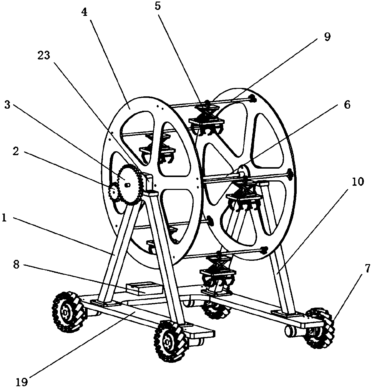
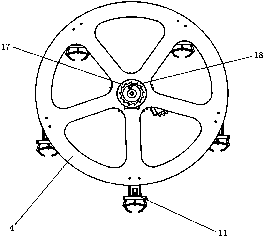
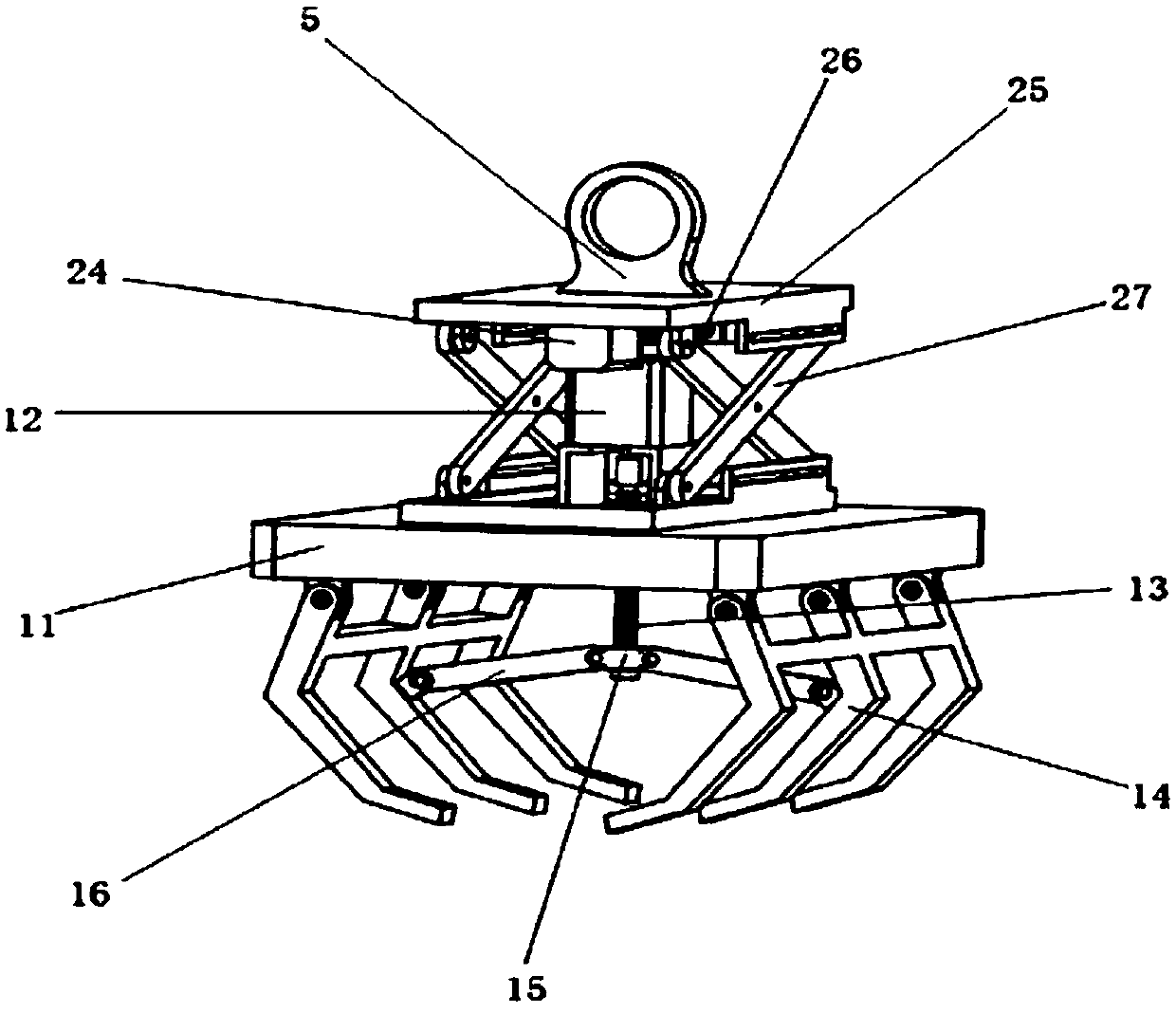
[0032] An airport luggage handling device, comprising a disc-type lifting mechanism, grippers 5 and a running mechanism, the bottom plate 19 is a “gate-shaped” member with an open front, and the wheel motor 20 is fixed to the lower part of the bottom plate 19 through a motor fixing part 21, The output shaft of the wheel motor 20 is fixed with the drive wheel 7 through the flange coupling 22, and the legs of the two herringbone supports 1 are respectively fixed with the upper surfaces of the left and right sides of the base plate 19, and the disc type lifting mechanism consists of two symmetrical circular Disc 4 and its connecting piece polished rod 9 are formed. The center of disc 4 is provided with a central shaft 6, and the two ends of the central shaft 6 are fixed to the tops of the herringbone brackets on the left and right sides t...


PUM


Abstract

The invention provides an airport baggage conveying device, and belongs to the technical fields of design and manufacture. A bottom plate is an n-shaped component of which the front portion is provided with an opening, an output shaft of each wheel motor is fixed to a driving wheel through a flange coupler, and legs of two herringbone brackets are fixed to the upper surface of the left side and the upper surface of the right side of the bottom plate respectively; a disc type lifting mechanism is composed of two symmetrical discs and connecting parts-polished rods thereof, a central shaft is arranged at the circle centers of the discs, the two ends of the central shaft are fixed to the top of the left herringbone bracket and the top of the right herringbone bracket through bearing pedestals, five polished rods are evenly distributed and fixed between the two discs along the circumference, and a gripper is fixedly connected to the middle of each polished rod in a matched mode through anear loop of a connecting base and a bearing; a small gear connected with an output shaft of a rotating motor is arranged on the side face of the left herringbone bracket, and the small gear meshes with a large gear arranged at the end of the central shaft; the right herringbone bracket is provided with a ratchet wheel self-locking mechanism; and a cross beam of the bottom plate is provided with apositioning controlling and vision sensing device. The airport baggage conveying device is mainly used for airport baggage conveying.

Description

technical field [0001] The invention belongs to the technical field of mechanical device design and manufacture, and in particular relates to airport luggage transportation equipment. Background technique [0002] With the gradual improvement of airport construction, the number of passengers who choose to fly every year continues to increase, which leads to relatively heavy luggage delivery operations, and the problem of luggage check-in methods is becoming more and more obvious, especially the problem of violent check-in and luggage loss. The current method is still manual handling. The efficiency of manual handling of checked luggage is very low, and the lack of direct tracking of luggage causes luggage to be easily lost, and duplication of labor is harmful to human physical and mental health, which inevitably leads to violent treatment of luggage. The development of unmanned intelligent handling devices is conducive to improving handling efficiency, reducing the rate of l...

Claims


Application Information

Patent Timeline
Patent Type & Authority Applications(China)
IPC IPC(8): B65G35/00B65G47/90B65G43/08
CPCB65G35/00B65G43/08B65G47/902B65G2203/044
Inventor 张祖涛管奇卉张庭生潘宏烨漆令飞朱勉宽潘亚嘉
Owner SOUTHWEST JIAOTONG UNIV
Why Eureka
Try Eureka