Power-driven power generation method for device assembled to running electric vehicle

A power-driven, electric vehicle technology, applied in the direction of electric vehicles, electric components, mechanisms that generate mechanical power, etc., can solve the problem of power consumption of the vehicle body, and achieve the effect of weight reduction and simple structure

Inactive Publication Date: 2018-03-20
林杨
View PDF0 Cites 3 Cited by
  • Summary
  • Abstract
  • Description
  • Claims
  • Application Information

AI Technical Summary

Problems solved by technology

[0002] Traditional electric vehicles rely on electric energy to drive, and the electric energy of electric vehicles usually comes from the battery. Theoretically, the heavier the car body, the more po

Method used


Image

  • Power-driven power generation method for device assembled to running electric vehicle
  • Power-driven power generation method for device assembled to running electric vehicle
  • Power-driven power generation method for device assembled to running electric vehicle

Examples


Embodiment Construction

[0031] The technical solution of the present invention will be described in detail below through the accompanying drawings and specific embodiments.

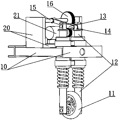
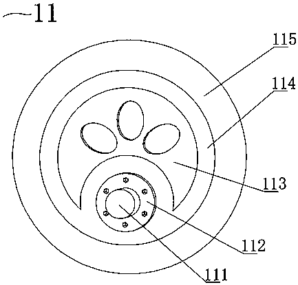
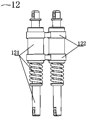
[0032] Such as Figure 1 to Figure 11 As shown, a power-driven power generation method assembled on an electric vehicle when driving, including a transmission device 1 and a power generation device 2, is characterized in that: the transmission device 1 includes an electric vehicle chassis 10, a cam wheel 11, a shaft 111, and a hub 112, wheel disc 113 retaining ring 114, tire 115, driver device 12, driver 121, drive shaft 1211, hole 12111, spring support ring 12112, hole 12113, spring 1212, sleeve 1213, spring limit ring 12131, shaft limit Ring 12132, fixed bracket 122, ferrule 1221, ferrule 1222, connecting rod 1223, shaft 13, push rod 14, straight notch shaft port 141, spline shaft port 142, spline shaft 15, spline 151, spline 152, gear 16, said devices are installed and fixed on the electric vehicle chassis 10, the two ends o...


PUM


Abstract

The invention belongs to a power-driven power generation method for a device assembled to a running electric vehicle. The power-driven power generation method comprises the steps that a cam wheel is driven when the electric vehicle runs, the cam wheel drives drive shafts of drivers, the drive shafts drive a shaft, the shaft drives a push rod, the push rod drives a spline shaft, the spline shaft drives a gear to drive a generator to generate electricity, and the generated electricity is used for charging the electric vehicle or supplying power to power consumption equipment through an electricenergy control module on the electric vehicle. According to the power-driven power generation method, a transmission device and a power generation device are included. The transmission device comprises an electric vehicle underframe, the cam wheel, a driver device, the shaft, the push rod, the spline shaft and the gear. The power generation device comprises a support seat, the generator, a gear and a one-way bearing. According to the device, the device cam wheel is mainly arranged at the bottom of the electric vehicle, the bottom end of a tire is in flush contact with the ground of an electricvehicle tire, and when the electric vehicle is a two-wheel vehicle, the electric vehicle is located between a front wheel and a rear wheel of the device cam wheel position and is close to the rear wheel; and when the electric vehicle is an electric vehicle with three or more wheels, the device cam wheel position is located between two rear wheels.

Description

technical field [0001] The invention belongs to a power-driven power generation method assembled on an electric vehicle when driving, specifically a cam wheel installed at the bottom of the frame of the electric vehicle. The momentary power drives the cam, and through the up and down reciprocating motion characteristics generated by the cam operation, it is driven by a mechanical device to drive the generator to generate electricity. Background technique [0002] Traditional electric vehicles rely on electric energy to drive, and the electric energy of electric vehicles usually comes from the battery. Theoretically, the heavier the car body, the more power is consumed when driving an electric vehicle with pure electric energy. The recycling of electric vehicles is currently limited to the recovery and utilization of the kinetic energy of electric vehicles when braking. Contents of the invention [0003] In order to solve the above technical problems, the present invention...

Claims


Application Information

Patent Timeline
IPC IPC(8): F03G7/00F03G3/00H02K7/116
CPCF03G3/00F03G7/00H02K7/116Y02T10/64
Inventor 杨林
Owner 林杨
Why Eureka
Try Eureka