Supercharging device for oil well metering station and supercharging method

A technology of pressurization device and metering station, which is applied in pipeline systems, mechanical equipment, gas/liquid distribution and storage, etc., can solve the problems of wasting effective resources, long oil pipelines, pipeline blockage, etc., and achieves convenient and fast construction and installation. High degree of digitalization and the effect of reducing oil well back pressure

Pending Publication Date: 2018-03-20
SHAANXI XINGCHEN PETROLEUM TECH
View PDF0 Cites 2 Cited by
  • Summary
  • Abstract
  • Description
  • Claims
  • Application Information

AI Technical Summary

Problems solved by technology

[0017] At the same time, due to various reasons such as the well group is far away from the pressurization station and metering station, the oil pipeline is long, and the oil wells are seriously waxed, the production of crude oil has been in a state of high back pressure (2.5-5MPa) for a long time, seriously affecting The normal production of the oil well is hindered, and the back pressure can reach 6-7MPa when the weather is cold in winter. Under such circumstances, the oil well can hardly produce normally
The external transportation process of the well group is generally a double-pipeline process, that is, one metering pipeline and one mixed transportation pipeline. During oil transportation in winter, the two pipelines must ensure uninterrupted oil transportation, as long as one pipeline stops oil transportation for one hour , it will cause pipeline blockage, waste effective resources, increase production costs, and increase labor intensity of workers

Method used


Image

  • Supercharging device for oil well metering station and supercharging method
  • Supercharging device for oil well metering station and supercharging method

Examples


Embodiment Construction

[0039] The present invention is described in further detail below in conjunction with accompanying drawing:

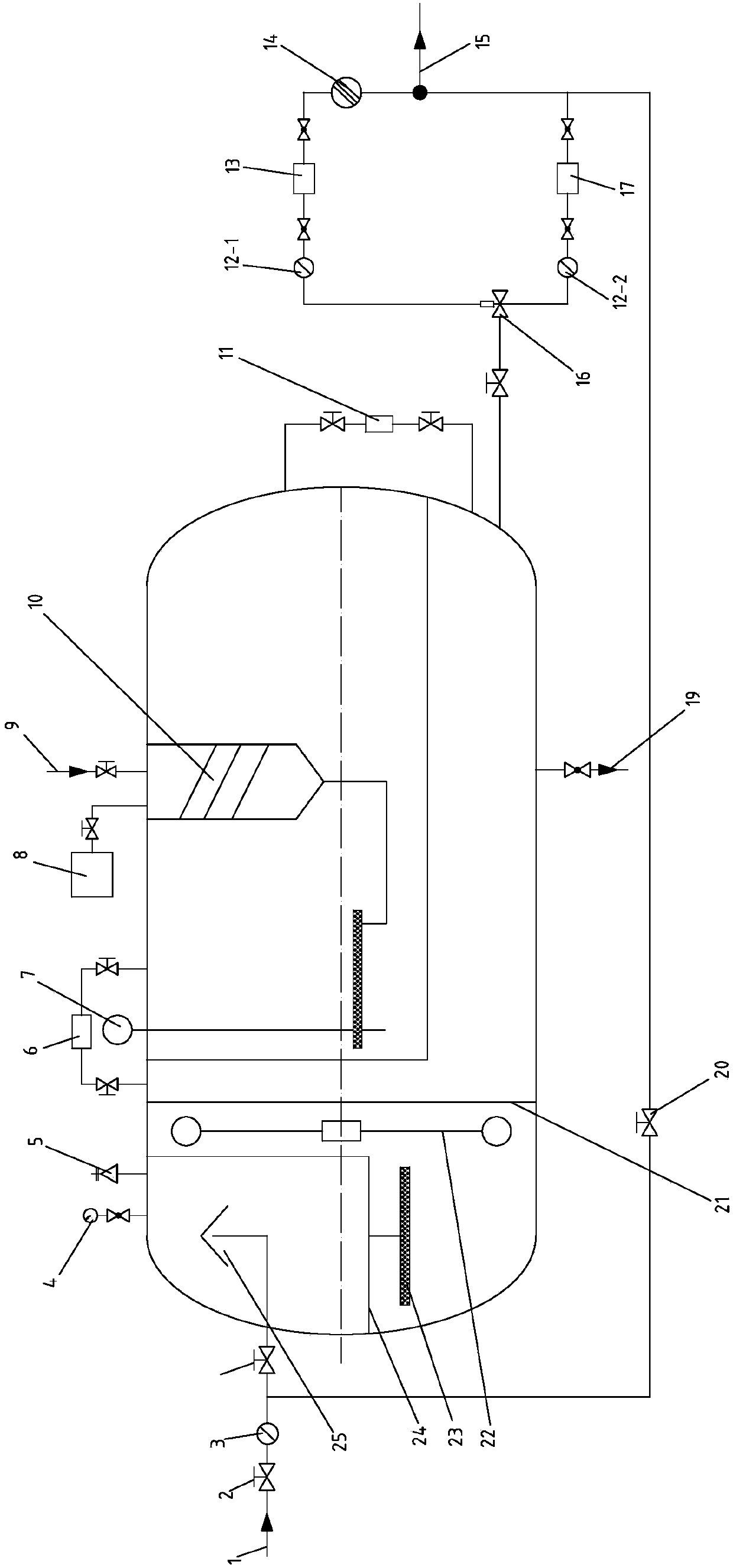
[0040] see figure 1: The present invention is used for the pressurization device of the oil well metering station, including a separator, and one end of the separator is connected to a multi-well liquid inlet pipeline 1, and oil, gas and water for the multi-well liquid inlet pipeline 1 are arranged in the separator Separation equipment; the other end of the separator is connected to a single well liquid inlet pipeline 9, and an oil-gas-water separation device for the liquid inlet of the single well liquid inlet pipeline 9 is arranged inside the separator; the lower end of the separator The oil-water outlet is connected to the inlet of the electric reversing valve 16 through a pipeline; the electric reversing valve 16 is provided with two outlets, and one outlet of the electric reversing valve 16 is connected to the first filter 12-1 through a pipeline. The inlet of a ...


PUM


Abstract

The invention discloses a supercharging device for an oil well metering station. The supercharging device for the oil well metering station comprises a separator; one end of the separator is connectedwith a multi-well liquid inlet pipeline; the separator is provided with oil-water separation equipment for liquid feeding of the multi-well liquid inlet pipeline; the other end of the separator is connected with a single-well liquid inlet pipeline; oil-water separation equipment for liquid feeding of the single-well liquid inlet pipeline is arranged in the separator; an oil-water outlet in the lower end of the separator is connected with an inlet of an electric reversing valve through a pipe; the electric reversing valve is provided with two outlets; one outlet of the electric reversing valveis connected to an inlet of a first supercharging pump through a pipe and a first filter; an outlet of the first supercharging valve is connected to an oil-water outlet pipeline; and the other outletof the electric reversing valve is connected to an inlet of a second supercharging valve through a second filter and a pipe; and an outlet of the second supercharging valve is connected to the oil-water outlet pipeline through a pipe. The supercharging device for the oil well metering station adopts an integrated prying structure, and is convenient and fast to construct and install on the spot; and the whole set of device adopts intelligent control to achieve high digital degree.

Description

technical field [0001] The invention belongs to the technical field of petroleum, and relates to oil, gas and water metering pressurization, in particular to a pressurization device and a pressurization method for an oil well metering station. Background technique [0002] The metering technology of low-yield oil wells has been studied for many years, but the problem has not been fundamentally solved. As the mature oilfield enters the high water cut period, it becomes more and more difficult to measure oil wells. Coupled with the development of production and the needs of operation and management, the requirements for oilfield metering technology are also increasing. Therefore, to seriously solve the problem of oilfield wellhead measurement and improve the current wellhead measurement accuracy and management level has become an important issue to be solved urgently in oilfield production. Attempt to modify the structure of the separator so as to further improve the process...

Claims


Application Information

Patent Timeline
IPC IPC(8): F17D1/14F17D3/18F17D3/01F17D5/00
CPCF17D1/14F17D3/01F17D3/18F17D5/00
Inventor 程世英
Owner SHAANXI XINGCHEN PETROLEUM TECH
Why Eureka
Try Eureka