Energy supply

An energy supply and current limiting device technology, applied in circuit devices, emergency protection circuit devices, and automatic disconnection emergency protection devices, etc., can solve the problems of dangerous induced voltage and difficult technical control, and achieve the effect of improving energy supply.

Active Publication Date: 2018-03-20
SIEMENS AG
View PDF8 Cites 3 Cited by
  • Summary
  • Abstract
  • Description
  • Claims
  • Application Information

AI Technical Summary

Problems solved by technology

But in this case extremely high and dangerous induced voltages develop on the secondary winding, which are technically difficult to control

Method used


Image

  • Energy supply
  • Energy supply
  • Energy supply

Examples


Embodiment Construction

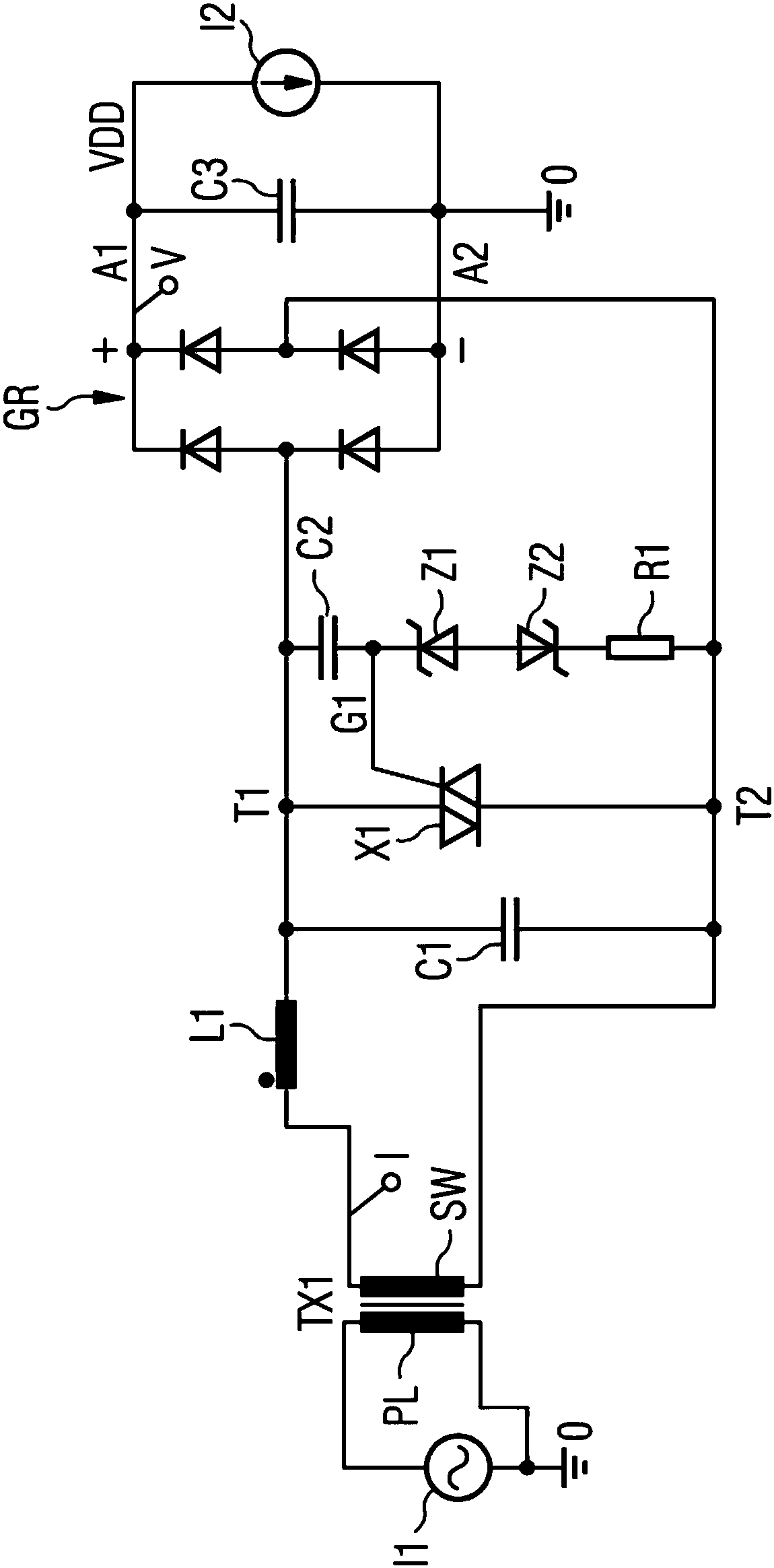
[0038] figure 1A first circuit of an energy supply device for an electrical circuit breaker is shown. On the primary side, the current transformer TX1 has a primary conductor PL which is part of an electrical circuit with an energy source I1 , which is monitored by a circuit breaker (not shown). On the secondary side, the current transformer has a secondary winding SW, which can have two or more connections. At the two connections of the secondary winding SW is connected a triac X1, which usually has two main connections T1, T2 and a control connection G1, also called gate connector. The two main connections T1 , T2 are connected in parallel to the two connections of the secondary winding SW, ie the main connection T1 is connected to one connection of the secondary winding and the main connection T2 is connected to the other connection of the secondary winding.

[0039] In principle, in a parallel circuit or in a series circuit means that further electrical components such ...


PUM


Abstract

An energy supply for an electrical circuit breaker includes a current converter with a primary conductor and a secondary winding. The energy supply further has a triac with two main connections and one control connection, the triac being connected electrically in parallel with the secondary winding via the main connections. A series circuit including at least two zener diodes is connected to the control connection of the triac at one end and to a main connection of the triac at the other end.

Description

technical field [0001] The invention relates to an energy supply device for a circuit breaker, in particular having a current transformer with a secondary winding for energy supply to the circuit breaker and whose primary side passes through the conductor configuration of the circuit breaker. The primary conductor is a conductor of a circuit, in particular a low-voltage circuit, to be monitored by the circuit breaker. [0002] The invention also relates to a DC current limiting device for an electrical circuit breaker. Background technique [0003] Low voltage refers to voltages up to 1000 volts AC or 1500 volts DC. [0004] A circuit breaker monitors the current flowing through it by means of a conductor and interrupts the current or energy flow to the energy sink or consumer, which occurs when a current limit value or a current time interval limit value is exceeded, that is, within a certain time interval. When the current value is exceeded, it is called triggering. Int...

Claims


Application Information

Patent Timeline
Patent Type & Authority Applications(China)
IPC IPC(8): H02H1/06H02H9/02H02H3/08
CPCH02H1/06H02H3/08H02H9/02H02H9/041H02H1/0007H02H3/025H02H3/083
Inventor M.盖斯勒M.施特勒
Owner SIEMENS AG
Why Eureka
Try Eureka