System and method for dynamic low-delay optimization

A low-latency, user-space technology, applied in the field of processor-based system operation, which can solve problems such as non-returning, user-space low-latency technology not being optimized, and blocking understanding.

Active Publication Date: 2018-03-20
HONG KONG APPLIED SCI & TECH RES INST
View PDF7 Cites 3 Cited by
  • Summary
  • Abstract
  • Description
  • Claims
  • Application Information

AI Technical Summary

Problems solved by technology

[0007] Similarly, user-space low-latency techniques are not optimized for any particular application, are implemented statically, and may or may not have any significant impact on the latency experienced by the application, depending on the resources used by the application. influences
For example, improving runtime performance by using optimized compilation options (for example, using the "-O3" compilation option of the GNU compiler toolchain) is applicable during compilation, but cannot be reverted to the original option during runtime.
In addition, existing user-space low-latency techniques are not tightly coupled with existing kernel-space low-latency techniques, so instead of providing low-latency optimizations for a combination of operating systems and applications, they try to address the operating system separately and independently and the latency of one of the applications
For example, a command line to be able to start / stop system services may be available to developers, but these command line tools are usually not accessible to application developers
Also, existing user-space low-latency techniques focus on application-related tasks rather than the entire data path
In addition, existing user-space low-latency techniques do not directly access processor-based system hardware or its information, but instead interface through a hardware abstraction layer (HAL) that blocks access to the understanding of specific hardware

Method used


Image

  • System and method for dynamic low-delay optimization
  • System and method for dynamic low-delay optimization
  • System and method for dynamic low-delay optimization

Examples


Embodiment Construction

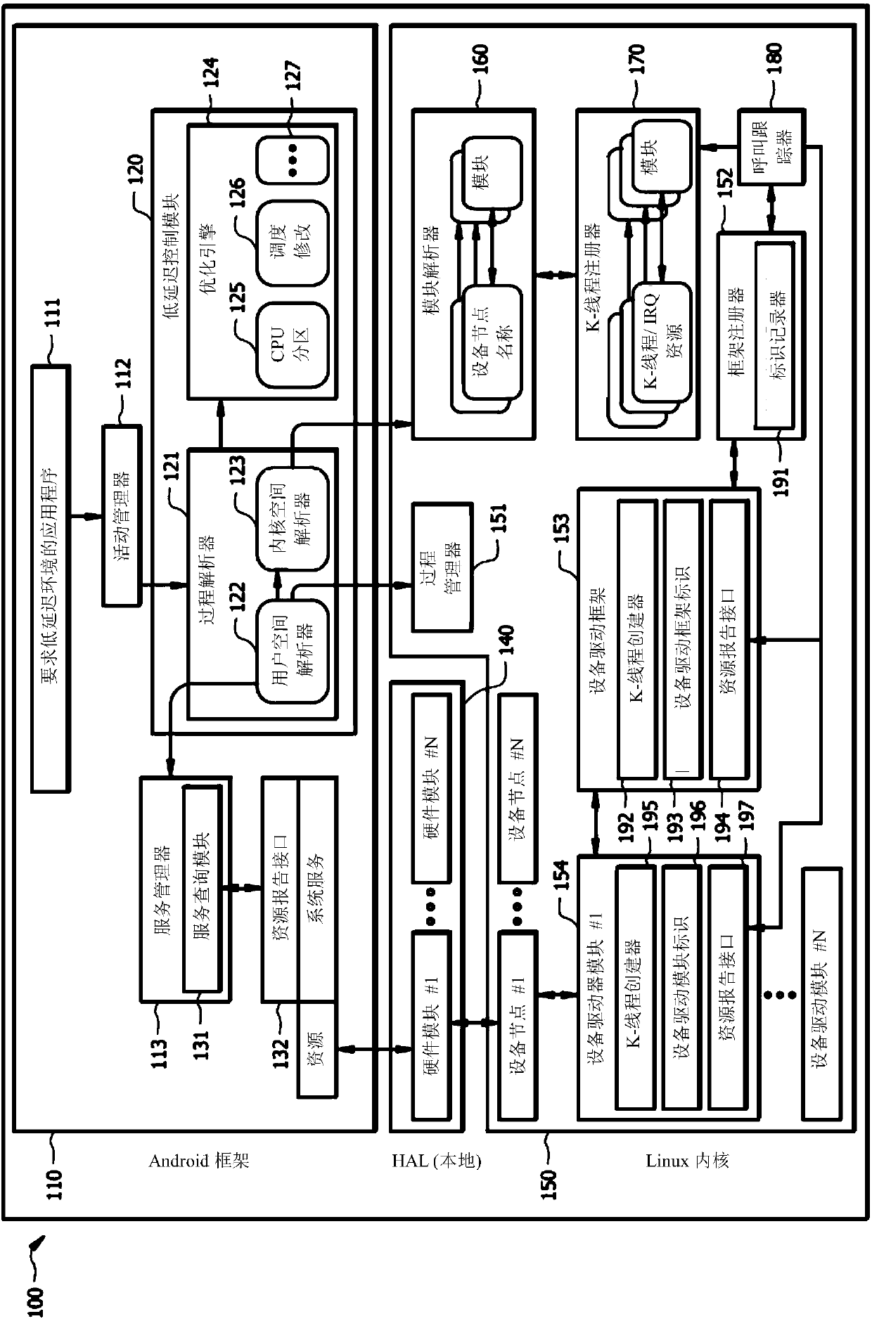
[0023] figure 1 A low-latency optimized implementation of one embodiment is shown that includes a multi-part configuration for obtaining information about the services and hardware used by an application and utilizing this information to provide dynamic implementation low-latency operation. specifically, figure 1 One embodiment of a processor-based system 100 (eg, a smartphone or other device with limited processing and / or other capabilities) is shown configured to optimize the low-latency operation of a particular application. figure 1 The low-latency optimized implementation configurations of the illustrated embodiments include modules implemented in user space (eg, the exemplary ANDROID framework of the illustrated embodiments) and kernel space (eg, the Linux kernel of the illustrated embodiments). Each of the modules cooperates together to obtain and provide information about the services and hardware used by the application to facilitate low-latency operation of the appl...


PUM


Abstract

The invention provides a system and method for low-delay optimization. The system and method are configured to be executed from a hardware layer of a whole operation system to an application program.Low-delay running implemented according to the embodiment is optimization aiming at a specific application program. The low-delay running is connected to specific hardware, implemented on the system based on a main processor and configured in low-delay optimization. For example, implementation of the low-delay optimization can involve various modules implemented in user space and kernel space, wherein these modules cooperate to obtain information of services and hardware related to application program use; and the information is provided for low-delay running of related application programs. During running in accordance with the embodiment, the low-delay running is started or forbidden dynamically by a type of low-delay optimization implementation; and based on each application program, the low-delay running can be conducted on the application program at proper time or according to needs.

Description

technical field [0001] The present invention relates to the operation of processor-based systems, and more particularly, to dynamic low-latency optimization with respect to the operation of processor-based systems. Background technique [0002] The use of various forms of processor-based platforms has exploded in recent years. For example, the use of processor-based personal communication and data processing platforms, commonly referred to as smartphones, has grown dramatically over the past few years and is expected to continue to grow for the foreseeable future. For example, in addition to providing cellular telephone communication services, smartphones are often used to provide data communications, data processing, viewing and / or creating streaming media, gaming and entertainment, and the like. Applications that can provide the aforementioned functionality range from those that use less processing power and other resources (eg, thin clients and simple web browser applica...

Claims


Application Information

Patent Timeline
IPC IPC(8): G06F9/50
CPCG06F9/5038G06F9/505
Inventor 卢振聪
Owner HONG KONG APPLIED SCI & TECH RES INST
Why Eureka
Try Eureka