

High-speed and heavy-duty large-space gantry mechanical arm truss guiding and driving device and application thereof
A driving device and manipulator technology, applied in the direction of manipulators, program-controlled manipulators, manufacturing tools, etc., can solve the problems of unsuitable large-span heavy-load movement, limited carrying capacity, high precision requirements, etc., and achieve good economic benefits and market value. Reasonable structural design, the effect of improving safety
- Summary
- Abstract
- Description
- Claims
- Application Information
AI Technical Summary
Problems solved by technology
Method used
Image

Examples
Embodiment 1
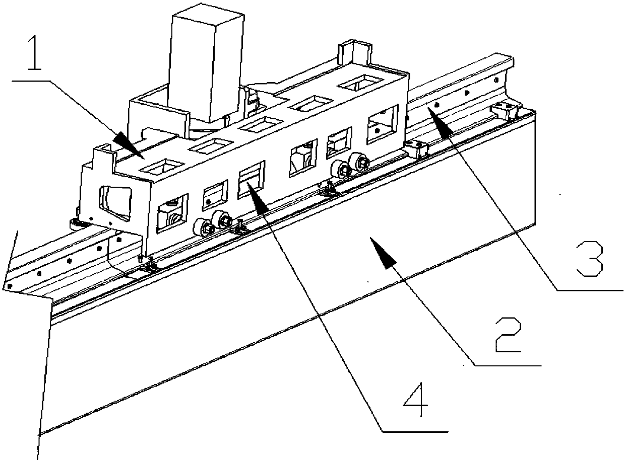
[0029] This embodiment provides a high-speed heavy-duty large-span gantry manipulator truss guide drive device, the whole guide drive device 1 is installed on the guide bearing guide rail 3 of the gantry manipulator frame 2; the whole guide drive device 1 includes a guide drive base 11, a motor Drive mechanism 13, transmission mechanism 4, bearing mechanism 12 and elastic guide mechanism 14, wherein bearing mechanism 12, elastic guide mechanism 14 are arranged on the relative both sides in the guide drive base 11, and motor drive mechanism 13 is arranged on guide drive base 11 outside one side and transmit the movement through the transmission mechanism 4.
[0030] Such as figure 2 As shown, the guiding and driving base 11 is a rectangular box-shaped rectangular frame structure, the upper surface is used for positioning and installing the moving truss, and the side and bottom surfaces are used for installing the bearing mechanism 12, the motor driving mechanism 13, the elasti...
Embodiment 2
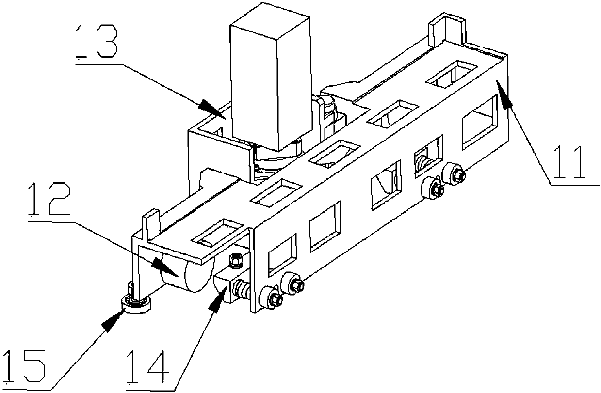
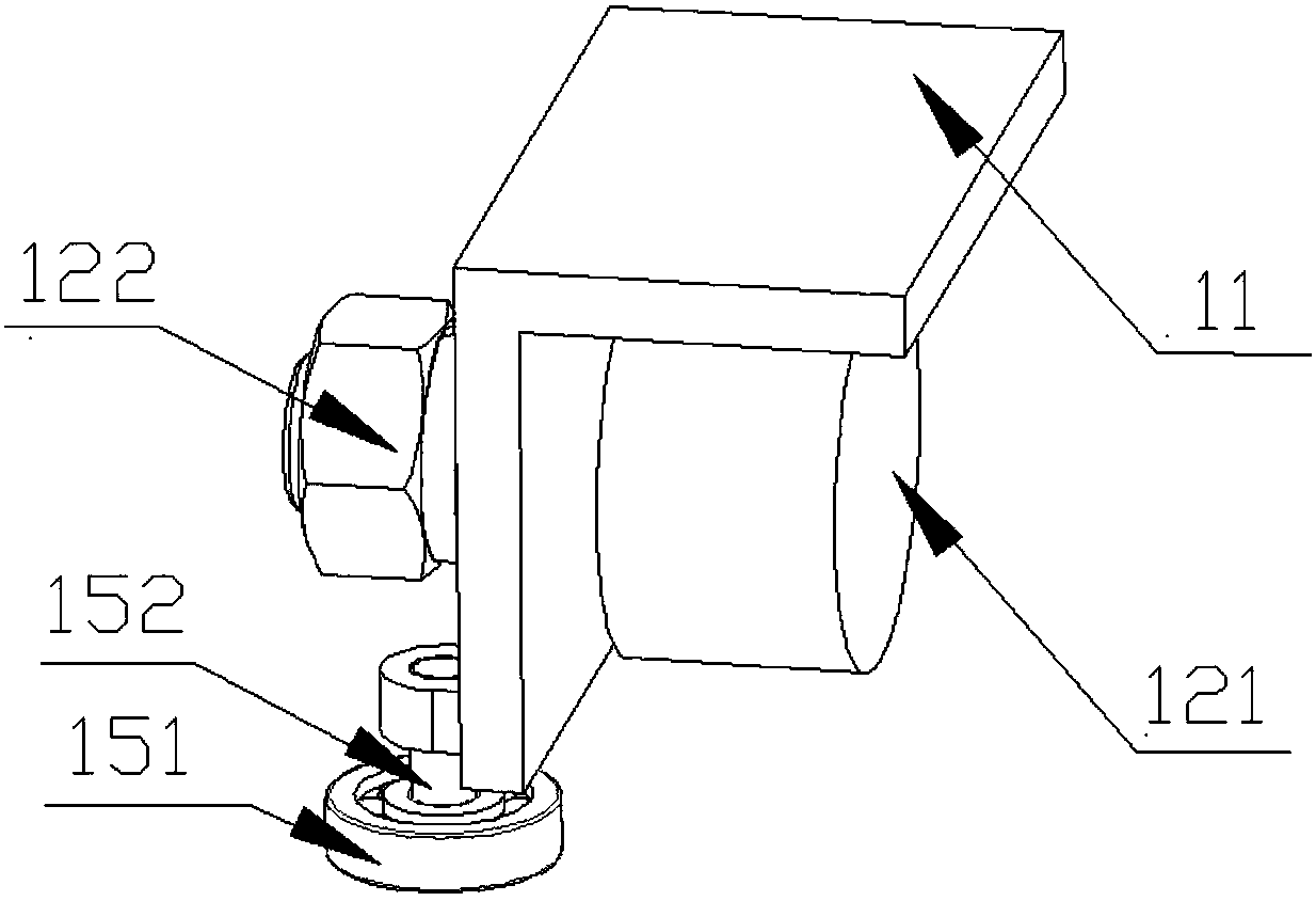
[0036] Such as image 3 As shown, this embodiment provides a high-speed heavy-duty large-span gantry manipulator truss guiding drive device, the structure is as described in Embodiment 1, the difference is that the guiding driving device 1 also includes a rigid guiding mechanism 15, the rigid guiding Mechanism 15 comprises rigid guide bearing 151 and rigid guide shaft 152, and rigid guide bearing 151 is fixed on the guide drive base 11 by rigid guide shaft 152 (one end of rigid guide shaft 152 is connected with guide drive base 11, and the other end is connected with rigid guide bearing 151 There is a certain gap between the rigid guide bearing 151 and the guide bearing guide rail 3, and the bearing is used to limit the truss hard to prevent the truss from deviating from the track during inclination measurement.
[0037]In this embodiment, two carrying mechanisms 12 and two rigid guiding mechanisms 15 are installed on one side of the guiding and driving base 11 , and two elast...
Embodiment 3
[0039] A method for using a high-speed, heavy-load, and large-span gantry manipulator truss guiding and driving device, using the guiding and driving device described in Embodiment 2, the specific operation process is as follows:
[0040] The whole guide drive device 1 is installed on the mobile phone frame 2, wherein the concentric load-bearing wheels 121 are placed on the guide bearing rail 3, and the elastic guide mechanism 14 and the rigid guide mechanism 15 are located on both sides of the guide bearing guide rail 3, wherein the rigid guide bearing 151 There is a gap between the eccentric guide wheel 141 and the guide bearing guide rail 3, and finally the gantry manipulator truss is positioned and installed on the upper surface of the guide drive base 11, and the motion is transmitted through the drive motor, the reducer 131 and the transmission mechanism 4, so that the entire The guide driving device drives the gantry manipulator truss to run.
PUM
 Abstract
Description
Claims
Application Information