
Crane power transmission device

A power transmission device and crane technology, applied in the directions of transportation and packaging, load hoisting components, etc., can solve the problems of complex structure of the center rotary joint, large layout space on the vehicle, difficult manufacturing and processing, etc., and solve the problem of chassis space occupation. , Solve the difficulty of manufacturing and processing, optimize the effect of the weight distribution of the whole machine

Pending Publication Date: 2018-03-23
ANHUI LIUGONG CRANE
View PDF0 Cites 0 Cited by
  • Summary
  • Abstract
  • Description
  • Claims
  • Application Information

AI Technical Summary

Problems solved by technology

[0004] The disadvantage is that the existing single-engine technology is only suitable for small and medium tonnage cranes, but the application of this technology to large tonnage cranes mainly has the following problems:
[0005] 1. The pressure loss is large due to the long length of the pipeline. Due to the increase in the boarding length of the large-tonnage crane, the corresponding mechanism is far away from the slewing center;
[0006] 2. The hydraulic oil tank and hydraulic oil pump need to be all arranged on the chassis, which takes up too much space on the chassis;
[0007] 3. The hydraulic channel of the central rotary joint increases more, resulting in a complex structure of the central rotary joint itself, which is difficult to manufacture and high in cost
[0009] 1. The dual-engine configuration requires two sets of independent air filters, radiators, mufflers and other engine accessories, which are heavy and costly
[0010] 2. The dual-engine configuration takes up a large layout space on the vehicle

Method used


Image

  • Crane power transmission device

Examples


Embodiment Construction

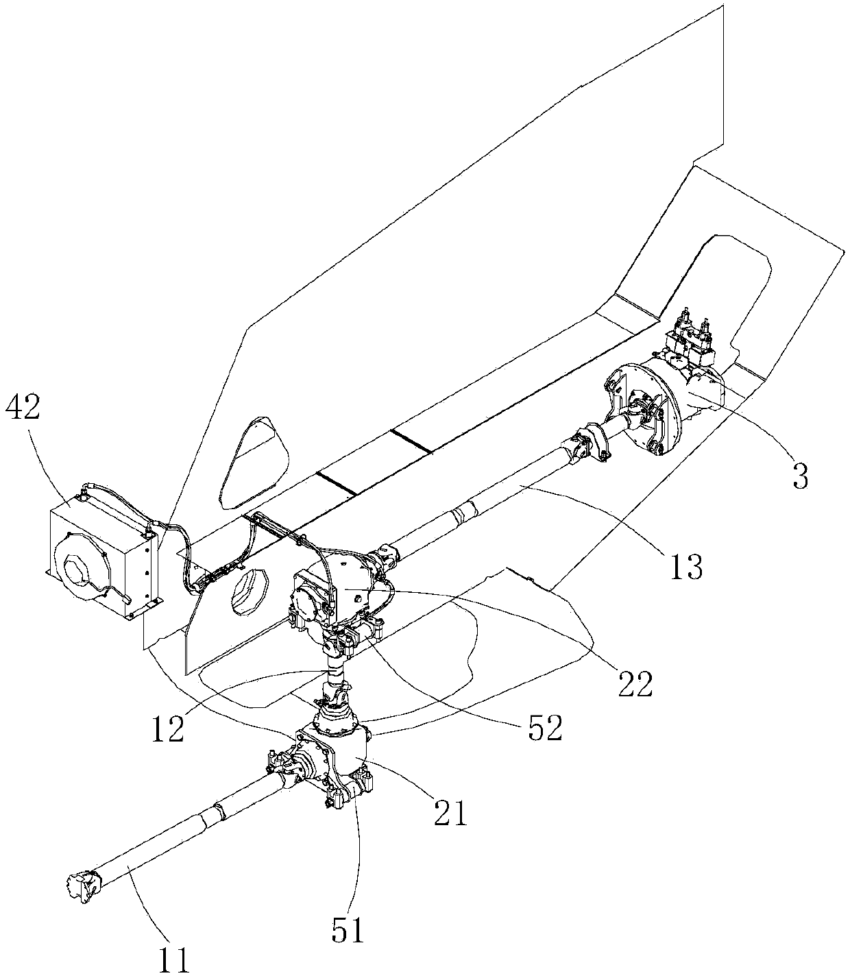
[0027] Such as figure 1 shown (for brevity of view, figure 1 The transfer case of the crane chassis and the clutch in the transmission device and the gear oil radiator 4 of the first angular transmission 21 are omitted in the figure.

[0028] The transmission device includes a clutch, three transmission shafts, two angular transmissions, two shock absorbers and two gear oil radiators 4 .

[0029] The three transmission shafts are the first transmission shaft 11, the second transmission shaft 12 and the third transmission shaft 13, and the two angular transmissions are the first transmission shaft 21 and the second transmission shaft 22, and the first transmission shaft 11 is horizontal Arranged in the chassis of the crane, one end of the first transmission shaft 11 is connected to the output shaft of the transfer case of the crane chassis through a clutch, and the other end of the first transmission shaft 11 is connected to the input shaft of the first angular transmission 21...


PUM


Abstract

The invention provides a crane power transmission device. The crane power transmission device comprises a first transmission shaft, a second transmission shaft, a third transmission shaft, a first angle driver and a second angle driver; one end of the first transmission shaft is connected with an output shaft of a crane chassis transfer case; the other end of the first transmission shaft is connected with an input shaft of the first angle driver; an output shaft of the first angle driver is connected with one end of the second transmission shaft; the other end of the second transmission shaftis connected with an input shaft of the second angle driver; an output shaft of the second angle driver is connected with one end of the third transmission shaft; and the other end of the third transmission shaft is connected with an oil pump of a hydraulic system of an upper car of a crane. The crane power transmission device is used for directly outputting power of a chassis of the crane to theupper car of the crane through a mechanical transfer mode; and the hydraulic system of the upper car is used for driving operation of a lifting mechanism, a revolving mechanism and an amplitude changemechanism of the upper car of the crane, so that the power transfer problem from the bottom to the upper car in a traditional high-tonnage crane is solved.

Description

technical field [0001] The invention relates to a crane power transmission device. Background technique [0002] The power of the existing small and medium tonnage cranes is to take power from the chassis transfer case, directly drive the hydraulic oil pump of the chassis through the transmission shaft, deliver the pressure oil to the central rotary joint through the hydraulic oil pipe, and then transport the pressure oil to the upper vehicle through the central rotary joint Hoisting mechanism, slewing mechanism, luffing mechanism and other loading mechanisms. [0003] Existing large-tonnage cranes all adopt a dual-engine power system, the chassis engine provides the driving power of the whole vehicle, and the upper-car engine provides the lifting operation power. The engine on the car drives the hydraulic oil pump through the transfer case to deliver the pressure oil to the hoisting mechanism, the slewing mechanism, the luffing mechanism and other on-board mechanisms. [...

Claims


Application Information

Patent Timeline
IPC IPC(8): B66C13/12
CPCB66C13/12
Inventor 何亚刚贾宏飞黄心顺
Owner ANHUI LIUGONG CRANE
Learn More