
Self-propelled road marking machine

A self-propelled, marking machine technology, applied in the direction of roads, roads, road repairs, etc., can solve the problems of low work efficiency, high labor intensity, slow work speed, etc., to achieve high marking accuracy, high degree of automation, and work high efficiency effect

Pending Publication Date: 2018-03-23
山东大道智慧交通股份有限公司 +1
View PDF8 Cites 3 Cited by
  • Summary
  • Abstract
  • Description
  • Claims
  • Application Information

AI Technical Summary

Problems solved by technology

[0002] At present, the domestic road marking equipment is generally a semi-automatic device controlled by manual operation or single-chip microcomputer. Its working speed is slow, the marking accuracy is low, the labor intensity is high, and the work efficiency is low, which can no longer meet the current development needs of road marking.

Method used


Image

  • Self-propelled road marking machine
  • Self-propelled road marking machine

Examples


Embodiment

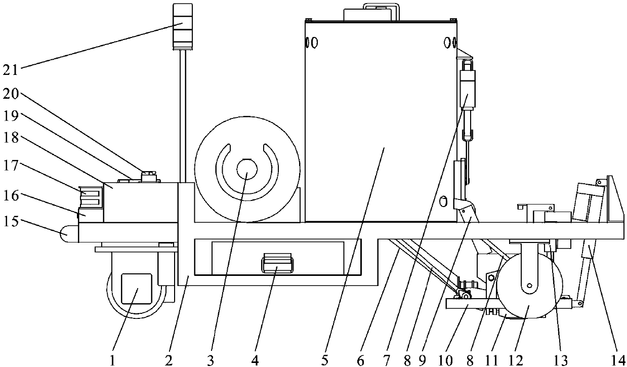
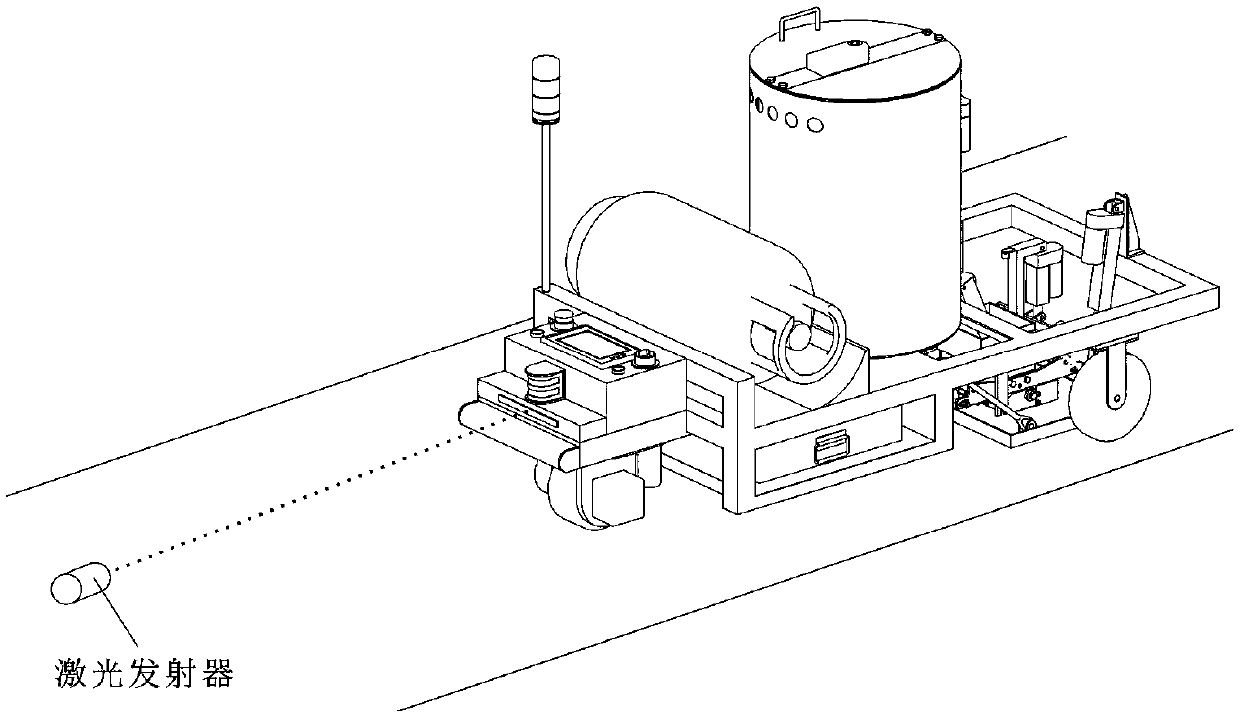
[0017] Such as figure 1 The self-propelled road marking machine structure shown includes a vehicle frame 2, a steering wheel 1 and two fixed casters 12 are installed on the bottom of the vehicle frame 2 to form a self-propelled tricycle with three-wheel support, front-wheel drive and steering; A battery pack 4 is installed in the middle of the frame 2; a laser receiver 16 is fixedly installed at the front of the frame 2; an obstacle sensor 17 is provided directly above the laser receiver 16; an electrical control box 18 is provided at the side of the laser receiver 16; The uppermost part of the vehicle frame 2 is equipped with an acousto-optic warning device 21; the upper middle position of the vehicle frame 2 is fixedly equipped with a paint bucket 5, and a flame nozzle is installed at the bottom of the paint bucket 5; a first electric push rod 7 is installed on the paint bucket 5, One end of the first electric push rod 7 is hingedly mounted on the outer wall of the paint buc...


PUM


Abstract

The invention relates to a self-propelled road marking machine structure. The self-propelled road marking machine structure comprises a vehicle frame, wherein a steering wheel and two fixed caster wheels are mounted at the lower part of the vehicle frame to form a self-propelled tricycle chassis structure which is supported by three wheels and is driven and realizes steering through the front wheel; a battery pack is mounted at the middle of the vehicle frame; a mechanical anti-collision device and a laser receiver are fixedly mounted in the forefront of the vehicle frame; an obstacle sensor is arranged directly above the laser receiver; an electrical control box is arranged on the side surface of the laser receiver; an audible and visual warning device is mounted at the top of the vehicleframe; a liquefied gas tank and a paint bucket are fixedly mounted at the middle position of the upper part of the vehicle frame; a marking hopper and a lifting device are mounted at the tail part ofthe vehicle frame; and flaming heads are mounted at the bottom of the paint bucket and the side surface of the hopper. The invention discloses a novel design scheme of a road marking machine and designs a self-propelled road marking machine high in automation degree, high in marking accuracy and high in work efficiency, so that the development needs of advanced road marking are further met.

Description

technical field [0001] The invention belongs to the technical field of road marking, and in particular relates to a self-propelled road marking machine. Background technique [0002] At present, domestic road marking equipment is generally a semi-automatic device controlled by manual operation or single-chip microcomputer. Its working speed is slow, the marking accuracy is low, the labor intensity is high, and the work efficiency is low, which can no longer meet the current development needs of road marking. Contents of the invention [0003] The purpose of the present invention is to overcome the above-mentioned defects in the prior art, and provide a self-propelled road marking machine with high degree of automation, high marking precision and high working efficiency. [0004] In order to achieve the above object, the technical solution of the present invention is as follows. [0005] A self-propelled road marking machine structure, including a frame, the lower part of ...

Claims


Application Information

Patent Timeline
Patent Type & Authority Applications(China)
IPC IPC(8): E01C23/24
CPCE01C23/24
Inventor 常军闫超白宗利葛明瑞刘尚王洪友张晓光孙孝臣葛坤孟广耀黄居鑫
Owner 山东大道智慧交通股份有限公司
Learn More