Water turbine based on combined type multi-stage tidal current energy power generation

A tidal current energy and compound technology, which is applied in the direction of ocean energy power generation, reaction engine, hydroelectric power generation, etc., can solve the problem of not being able to make good use of the energy of the water passing through the runner, not being able to play a good role in gathering energy, and not being able to provide Output power and other issues to achieve the effect of improving the inflow effect, stabilizing the water flow, and increasing the output of the runner

Active Publication Date: 2018-03-23
HOHAI UNIV +1
View PDF7 Cites 2 Cited by
  • Summary
  • Abstract
  • Description
  • Claims
  • Application Information

AI Technical Summary

Problems solved by technology

However, this solution still has the following deficiencies: first, the structure of the shroud is simple, and it cannot play a good role in gathering energy, which directly affects economic performance; second, it belongs to a single-stage ocean current energy turbine, and the efficiency of using ocean current energy to generate electricity is low
Although this scheme can efficiently convert ocean kinetic energy under bidirectional currents, it still has the following deficiencies: first, it belongs to a single-stage ocean current energy turbine, and the efficiency of using ocean current energy to generate electricity is low; second, the blade design of the turbine is still traditional. The design theory of the airfoil is too simple to make good use of the water energy flowing through the runner.
Although the use of the shroud improves the energy gathering effect of the tidal current energy, there are still the following deficiencies: First, the vertical axis blade adopts a single elliptical blade design, which cannot provide efficient output power; second, it belongs to a single-stage ocean current energy turbine. The efficiency of ocean current power generation is low

Method used


Image

  • Water turbine based on combined type multi-stage tidal current energy power generation
  • Water turbine based on combined type multi-stage tidal current energy power generation
  • Water turbine based on combined type multi-stage tidal current energy power generation

Examples


Embodiment 1

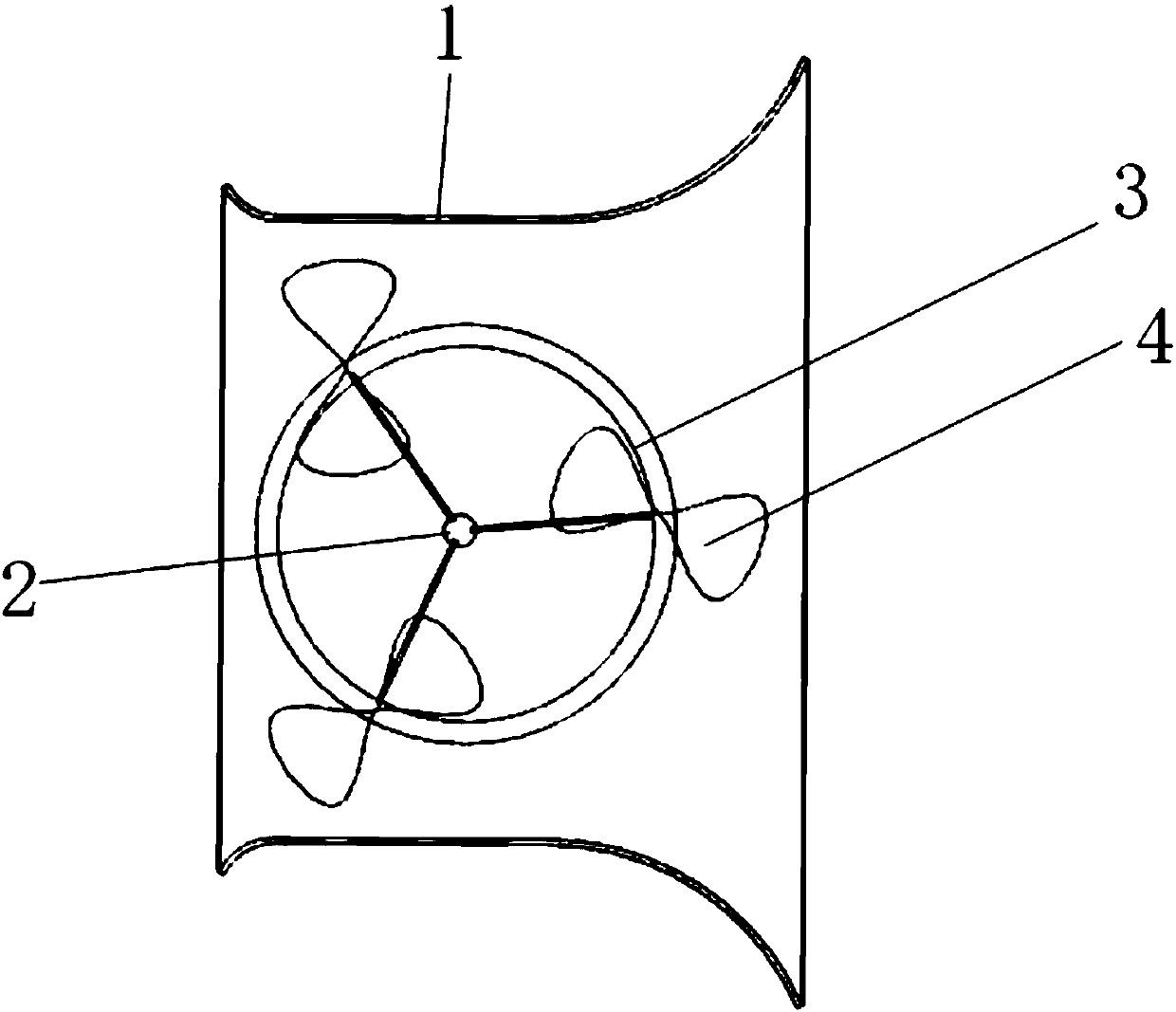
[0028] combine Figure 1 to Figure 4 , a kind of hydro turbine based on composite multi-stage tidal current energy generation proposed by the present invention is characterized in that: it includes a runner 1, a bearing support frame 3, a rotating shaft 2 and an impeller, and the impeller includes a plurality of pears Shaped line airfoil blade 4; the runner is fixedly arranged at 2 / 3 of the middle section of the wind deflector 1, and the two ends of the wind deflector 1 are trumpet-shaped, the inlet is thin, the outlet is thick, and the middle section is a straight line type, the top and the bottom of the shroud 1 are horizontal planes; the pear-shaped airfoil blade 4 is centered on the rotating shaft 2 on the blade fixing plate, and the space of the pear-shaped airfoil blade 4 is circumferentially distributed, and The bearing support frame 3 is welded and fixed; the coordinates of the key points of the pear-shaped airfoil blade 4 are expressed in the following manner, X repre...

Embodiment 2

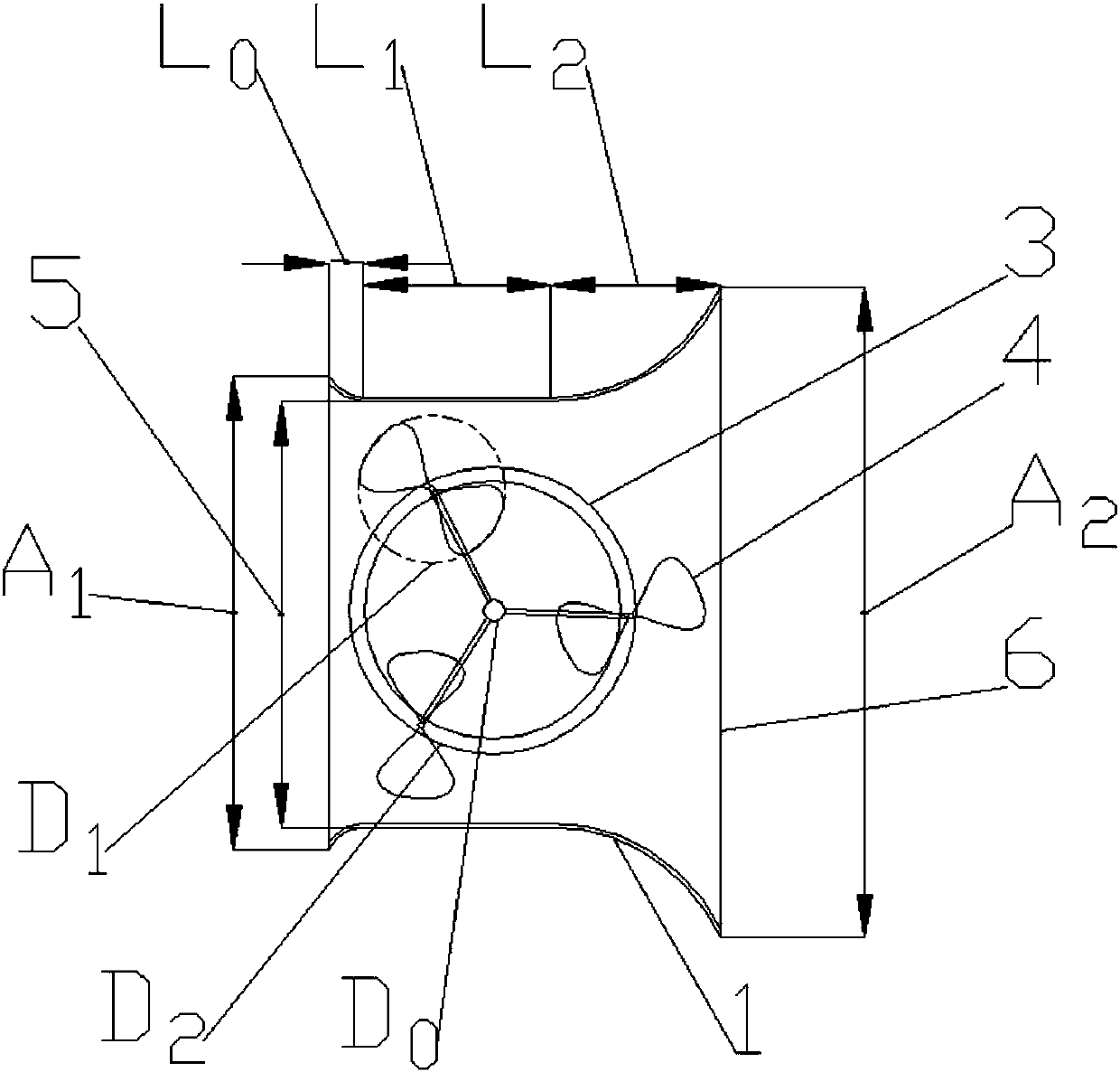
[0033] combine figure 1 and figure 2 , the shape of the rotating shaft 2 in the present invention is cylindrical, and the diameter D of the rotating shaft 2 0 with impeller diameter D 1 The ratio of 0.08 to 0.15, the diameter D of the rotating shaft 2 0 and runner diameter D 2 The ratio of 0.065 ~ 0.077.

Embodiment 3

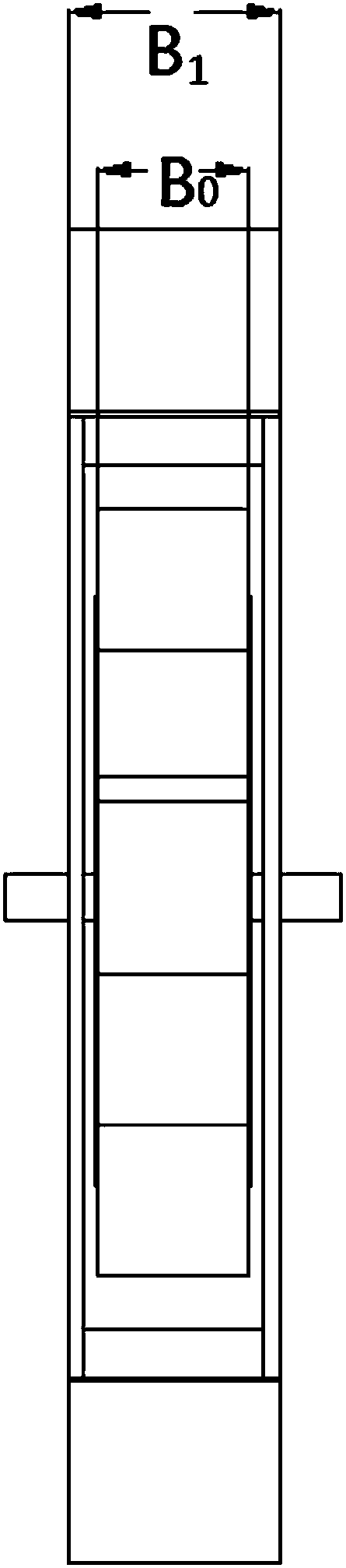
[0035] combine figure 2 and image 3 , the length L of the inlet section of the shroud 1 according to the present invention 0 and the length L of the middle section of the shroud 1 1 The ratio of 0.08 to 0.15, the length L of the outlet section 6 of the shroud 1 2 The length L of the middle section of the shroud 1 1 The ratio of 0.51 to 0.58; the width A of the inlet section 5 of the shroud 1 1 with the width A of the middle section of the spoiler 1 0 The ratio of 1.05 to 1.11, the width A of the outlet section 6 of the shroud 1 2 with the width A of the middle section of the spoiler 1 0 The ratio is 1.47 ~ 1.54; the height of the runner B 0 Height B with respect to spoiler 1 1 The ratio is 0.65-0.71.

[0036] Each interface of the wind deflector 1 perpendicular to the incoming flow direction is rectangular, and the heights of each rectangle are equal. In the interface perpendicular to the incoming flow direction, the vertical symmetry between the wind deflector 1 and ...


PUM


Abstract

The invention relates to a water turbine based on combined type multi-stage tidal current energy power generation. The water turbine comprises a flow guide cover and a rotating wheel composed of a bearing supporting frame, a rotating shaft and an impeller. The impeller comprises a plurality of pyriform line wing type blades, the rotating wheel is fixedly arranged at the 2/3 position of the middlesection of the flow guiding cover, and the two ends of the flow guiding cover are each in a horn shape, wherein an inlet of the flow guiding cover is slim, and an outlet of the flow guiding cover is thick. The middle section is in a leaner shape, and the top and the bottom of the flow guiding cover are both the horizontal plane. The pyriform line wing type blades take the rotating shaft as the center on a blade fixing plate and circumferentially distributed in space and welded and fixed to the bearing supporting frame, and X and Y represent the spatial coordinate values of a key point on the section wing type curve of one single pyriform line wing type blade correspondingly. The water turbine is simple in structure and high in efficiency, can be used for sea tidal current energy power generation and can also be used for power generation under the micro tidal current energy conditions such as mountains, plains, mountain springs, small reservoirs and streams.

Description

technical field [0001] The invention belongs to the technical field of fluid machinery and hydropower engineering equipment, in particular to a water turbine based on compound multi-stage tidal current energy generation. Background technique [0002] Countries in the world today put the development of hydropower in the priority position of energy development. The total amount of hydropower resources in my country is very rich. There are not only medium and high water head resources, but also low water head resources (including tidal current energy) of about 0.8 to 100 million kilowatts. The development and utilization of new energy, especially the development and utilization of marine energy for power generation, has great potential. development potential. Ocean current energy generates electricity by relying on the impact of the ocean tide to rotate the water turbine at high speed, and then drive the generator to generate electricity. It does not require a high water head t...

Claims


Application Information

Patent Timeline
Patent Type & Authority Applications(China)
IPC IPC(8): F03B13/26F03B3/12F03B3/18
CPCF03B3/121F03B3/18F03B13/264Y02E10/20Y02E10/30
Inventor 张玉全李东阔郑源臧伟
Owner HOHAI UNIV
Why Eureka
Try Eureka