Self-adaptive imaging device and method

An imaging device, self-adaptive technology, applied in measuring devices, material analysis through optical means, instruments, etc., can solve the problems of reducing imaging effect and recognition accuracy, and not considering

Pending Publication Date: 2018-03-23
苏州蛟视智能科技有限公司
View PDF11 Cites 0 Cited by
  • Summary
  • Abstract
  • Description
  • Claims
  • Application Information

AI Technical Summary

Problems solved by technology

[0004] Existing imaging systems do not consider how to select the appropriate wavelength according to the characteristics of air or water to increas

Method used


Image

  • Self-adaptive imaging device and method
  • Self-adaptive imaging device and method
  • Self-adaptive imaging device and method

Examples


Embodiment 1

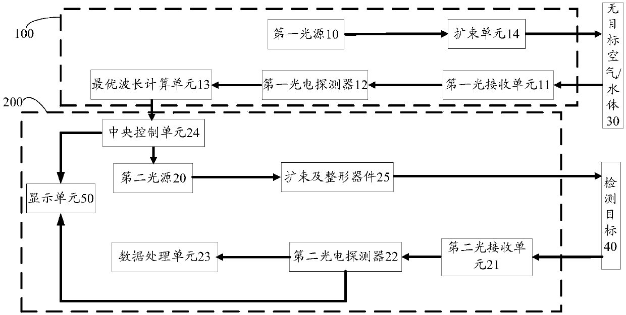
[0041] Such as figure 1 As shown, the present invention provides an adaptive imaging device, including an optimal wavelength estimation system 100 and an imaging system 200 .

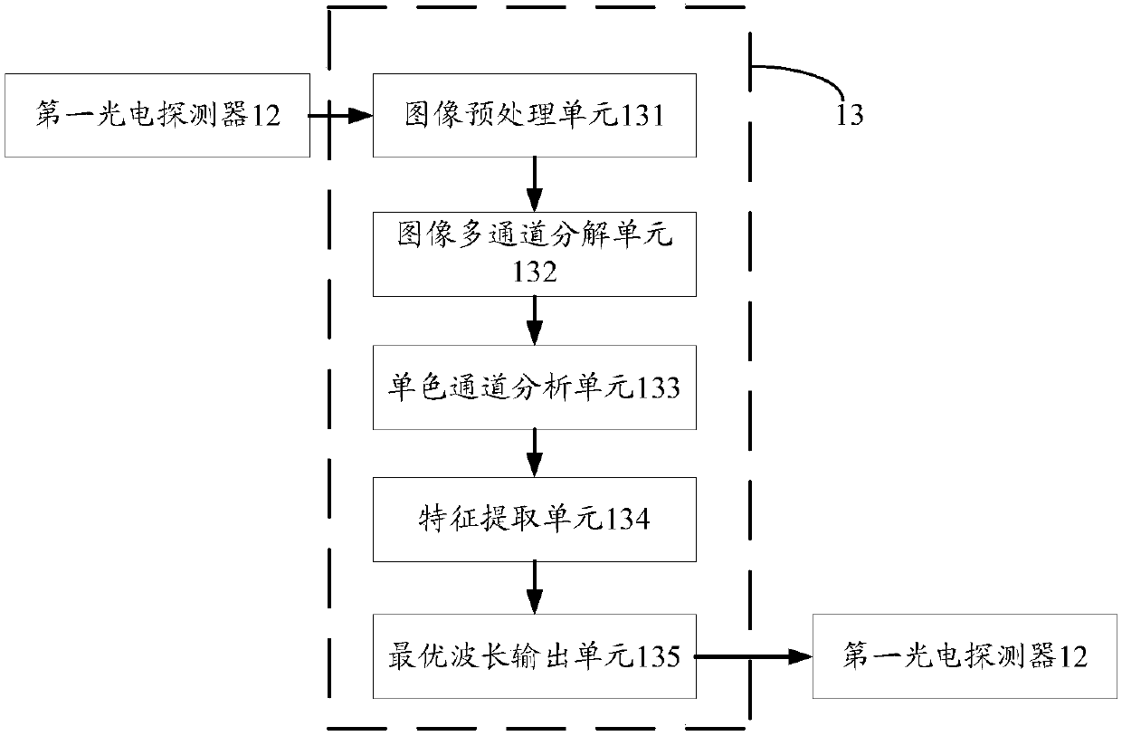
[0042]The optimal wavelength estimation system 100 includes a first light source 10, a first light receiving unit 11, a first photodetection unit 12, and an optimal wavelength calculation unit 13. The first light source 10, the non-target air / water body 30, The first light receiving unit 11, the first photodetection unit 12 and the optimal wavelength calculation unit 13 are arranged in sequence along the optical path. The first light source 10 is a wide-spectrum light source, and it is required to have good collimation and a small divergence angle, which can be A laser array composed of multiple laser light sources can also be a light source based on LARP (Laser Remotely Excited Phosphor Powder) technology. Specifically, the first light source 10 is also provided with a beam expander unit 14 behind the...

Embodiment 2

[0059] Different from Embodiment 1, in this embodiment, the second light source 20 includes several monochromatic light sources with different wavelengths, each of which is connected to the central control unit 24 . In practical application, in order to keep the structure of the system compact, the monochromatic light sources of different wavelengths can be arranged in a certain way to form an array. When the central control unit 24 obtains the information of the optimal wavelength, it controls the monochromatic light sources of corresponding colors to emit light.

Embodiment 3

[0061] Different from Embodiment 1-2, in this embodiment, the second light source 20 includes a wide-spectrum light source and a rotating filter located behind the wide-spectrum light source along the optical path, and the rotating filter is connected to the The central control unit 24 is connected. Specifically, the central control unit 24 controls the rotation of the rotary filter according to the information of the optimal wavelength, so that the light of the optimal wavelength passes through to form a detection beam, while the light of other wavelengths is filtered out.


PUM


Abstract

The invention discloses a self-adaptive imaging device and a self-adaptive imaging method. The device comprises an optimal wavelength estimating system and an imaging system; the optimal wavelength estimating system comprises a first light source, a first light receiving unit, a first photoelectric detection unit and an optimal wavelength calculating unit; the first light source, a target-free air/water body, the first light receiving unit, the first photoelectric detection unit and the optimal wavelength calculating unit are orderly aligned along the light path; the first light path is wide spectroscopic light source; the imaging system comprises a second light source, a second light receiving unit, a second photoelectric detection unit, a data processing unit and a central control unit.Through estimating the air/water environment where the target locates by the optimal wavelength estimating system before detecting the target, the optimal wavelength solution under the environment isacquired; the second light source is controlled through the central control unit, thus the output of the optimal wavelength or approximate optimal wavelength is realized; the light beam with optimal wavelength is applied to image the detecting target, thus the imaging distance is improved, and the best imaging quality is acquired on the same imaging distance.

Description

technical field [0001] The invention relates to the field of target detection, recognition and imaging, in particular to an adaptive imaging device and method. Background technique [0002] Most of the substances contained in air, especially heavily polluted air or water, absorb light, but different substances have obvious spectral characteristics in absorbing light. The content of various substances in the air or water of different pollution sources is very different, so the absorption attenuation of various substances in the air or water of different pollution sources contributes differently to the total attenuation coefficient, and the absorption characteristics of the spectrum are also different. larger. [0003] For example, in seawater, the content of suspended particulate matter and planktonic algae is relatively small, and soluble organic matter plays a major role in absorption. Studies have shown that the absorption of light waves by soluble organic compounds show...

Claims


Application Information

Patent Timeline
IPC IPC(8): G01N21/01
CPCG01N21/01Y02A90/30
Inventor 黄帆韩捷飞初宁蔡栋龙涛邹诚
Owner 苏州蛟视智能科技有限公司
Why Eureka
Try Eureka