
Image defogging method and device, storage medium, electronic equipment

A technology in images and images, applied in the field of image processing, can solve problems such as unreachable effects, poor image processing effects in dense fog, color distortion, etc.

Active Publication Date: 2020-10-02
XIAN TIANHE DEFENCE TECH
View PDF4 Cites 0 Cited by
  • Summary
  • Abstract
  • Description
  • Claims
  • Application Information

AI Technical Summary

Problems solved by technology

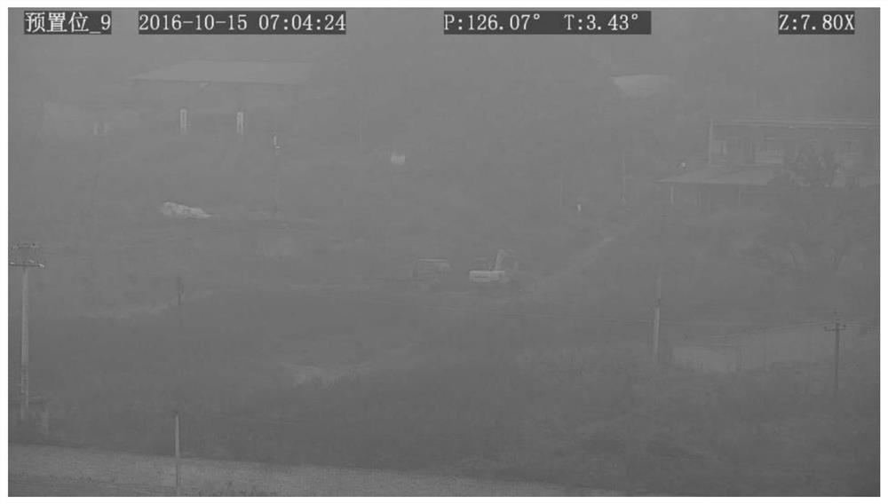
However, when there is a sky region in the image, since the sky region does not meet the prior conditions, the sky region in the defogged image obtained by this method will appear color distortion
In addition, the current image defogging method also includes using gradient information to segment the sky area, but when the concentration of fog is high, this method may misclassify the area similar to the sky area into the sky area, for example, in the concentration of fog When it is large, a large area of ​​field may be wrongly divided into sky regions. Therefore, only using gradient information to segment the sky region cannot achieve the desired effect
In addition, most of the current defogging methods are good for light fog images, but poor for dense fog images, and will produce obvious halo effects in places where the depth of the scene changes rapidly.

Method used


Image

  • Image defogging method and device, storage medium, electronic equipment
  • Image defogging method and device, storage medium, electronic equipment
  • Image defogging method and device, storage medium, electronic equipment

Examples


Embodiment Construction

[0075] Example embodiments will now be described more fully with reference to the accompanying drawings. Example embodiments may, however, be embodied in many forms and should not be construed as limited to the embodiments set forth herein; rather, these embodiments are provided so that this disclosure will be thorough and complete, and will fully convey the concept of example embodiments to those skilled in the art. The same reference numerals denote the same or similar parts in the drawings, and thus their repeated descriptions will be omitted.

[0076] Furthermore, the described features, structures, or characteristics may be combined in any suitable manner in one or more embodiments. In the following description, numerous specific details are provided in order to give a thorough understanding of embodiments of the present disclosure. However, those skilled in the art will appreciate that the technical solutions of the present disclosure may be practiced without one or mo...


PUM


Abstract

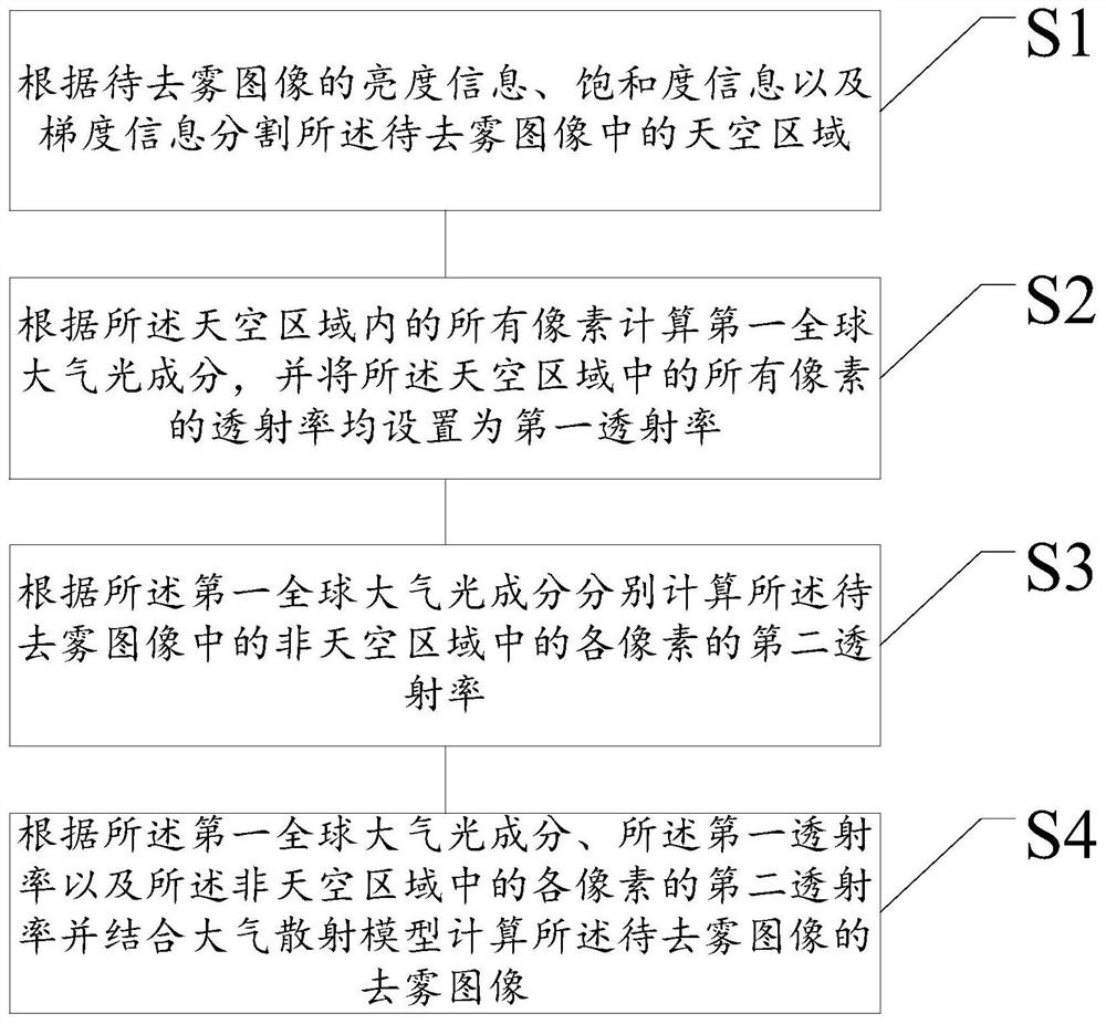
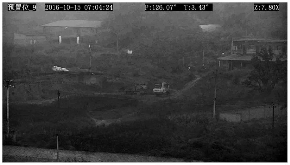
The present disclosure relates to the field of image processing technology, and in particular, to an image defogging method and device, storage media, and electronic equipment. The method may include: segmenting the sky area in the image to be dehazed according to the brightness information, saturation information and gradient information of the image to be dehazed; calculating the first global atmospheric light component based on all pixels in the sky area, and dividing the sky area into The transmittance of all pixels is set to the first transmittance; the second transmittance of each pixel in the non-sky area in the image to be dehazed is calculated according to the first global atmospheric light component; according to the first global atmospheric light component, The first transmittance and the second transmittance of each pixel in the non-sky area are combined with an atmospheric scattering model to calculate a dehazed image of the image to be dehazed. The present disclosure improves the accuracy of sky area segmentation, avoids color distortion in the sky area, and retains more detailed information in non-sky areas, making the dehazed image clearer and more natural.

Description

technical field [0001] The present disclosure relates to the technical field of image processing, and in particular to an image defogging method and device, a storage medium, and electronic equipment. Background technique [0002] In smoggy weather, there are a large number of suspended particles floating in the atmosphere, and these suspended particles have the effect of absorbing and scattering light. Therefore, in the foggy environment, especially in the case of heavy fog, the image captured by the visible light imaging system will have low contrast, color distortion, blurring and other degradation phenomena. This not only affects people's visual effects, but also brings serious security risks to various outdoor video surveillance, such as traffic surveillance. Therefore, how to obtain a clear defogged image has great application value. [0003] At present, image defogging methods can be roughly divided into two categories: one is based on traditional image enhancement ...

Claims


Application Information

Patent Timeline
Patent Type & Authority Patents(China)
IPC IPC(8): G06T5/00G06T7/11G06T7/187
CPCG06T7/11G06T7/187G06T2207/10024G06T2207/10016G06T2207/30232G06T5/73
Inventor 韩雪云胡锦龙
Owner XIAN TIANHE DEFENCE TECH
Learn More