Automatic coating apparatus and operation method thereof
An automatic coating and swinging device technology, which is applied to the surface coating liquid device, coating, etc., can solve the problems of automatic coating, uneven coating, low efficiency, etc., and achieve automatic coating, Uniform coating effect
- Summary
- Abstract
- Description
- Claims
- Application Information
AI Technical Summary
Problems solved by technology
Method used
Image
Examples
Embodiment 1
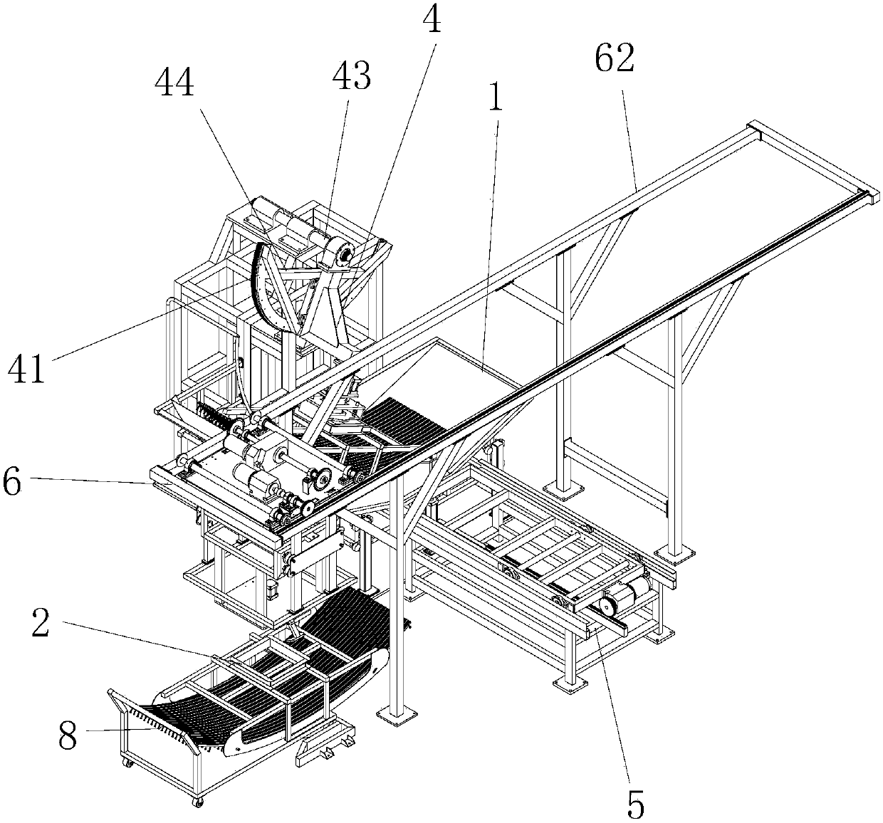
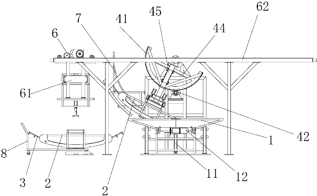
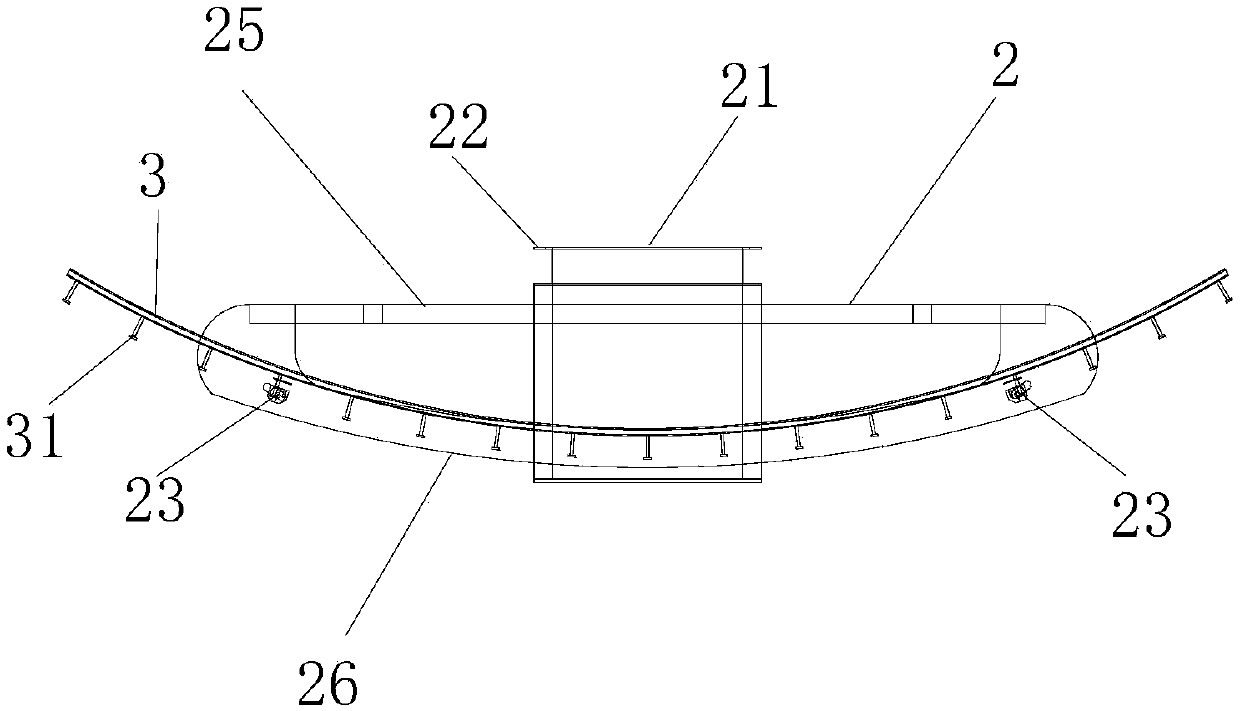
[0029] Embodiment 1 Taking the pre-buried channel in tunnel construction as an example, the automatic coating device of the present invention is introduced. Such as Figure 1 to Figure 2 As shown, the automatic coating device of the present embodiment includes a paint bucket 1, a fixed tooling 2, a swing device 4, a conveying device 5 and a feeding device 6; as image 3 and Figure 4 As shown, the fixed tooling 2 is a semi-cylindrical frame-type fixed tooling, and the frame-type fixed tooling 2 includes a plurality of straight frames 25 successively connected to form a rectangular frame, and two arc-shaped frames 26 forming a cylindrical frame; A connecting top plate 21 is arranged on the frame, and the edge of the connecting top plate 21 protrudes to form a pressing part 22; the two ends of a plurality of arc-shaped embedded channels 3 are lapped on the straight frame 25 at both ends of the rectangular frame, An installation baffle 23 is arranged axially between the two arc...
Embodiment 2
[0036] The working method of above-mentioned automatic coating device, comprises the steps:
[0037] A. Clamp the pre-embedded channel 3 to be coated on the inner side of the cylinder of the frame-type fixed tooling 2, use the trolley 8 to transport the frame-type fixed tooling 2 to the bottom of the manipulator 61, and the manipulator 61 grabs the fixed tooling 2 and transports it to on the carriage 52.
[0038] B. Start the first motor 55 to rotate in the forward direction, and drive the second gear 56 to rotate, thereby driving the first pulleys 54 on both sides of the sliding frame 52 to slide toward the front in the transverse concave groove 53 of the fixed frame 51 .
[0039] C. Start the lower pressure cylinder 40, push the L-shaped clamping block 49 on the lower end surface of the lower pressure plate 48 away from the bottom plate 46, so that there is a gap between the L-shaped clamping block 49 and the bottom plate 46; the fixed tooling 2 slides to the top of the pain...
PUM
 Abstract
Description
Claims
Application Information
 - R&D
- Intellectual Property
- Life Sciences
- Materials
- Tech Scout
- Unparalleled Data Quality
- Higher Quality Content
- 60% Fewer Hallucinations
Browse by: Latest US Patents, China's latest patents, Technical Efficacy Thesaurus, Application Domain, Technology Topic, Popular Technical Reports.
© 2025 PatSnap. All rights reserved.Legal|Privacy policy|Modern Slavery Act Transparency Statement|Sitemap|About US| Contact US: help@patsnap.com


