Punching device for building

A punching device and technology for construction, applied in the direction of feeding device, boring/drilling, drilling/drilling equipment, etc., can solve the problem of holes that are not suitable for a large number of continuous building decorative panels, affecting people's health, and punching Low precision and other issues, to achieve the effect of convenient drilling, easy replacement, and stability

Inactive Publication Date: 2018-03-27
广西南宁旭兆建筑工程技术有限公司
View PDF7 Cites 0 Cited by
  • Summary
  • Abstract
  • Description
  • Claims
  • Application Information

AI Technical Summary

Problems solved by technology

[0002] Building decorative board is a kind of building decoration material, which is widely used. The building decorative board needs to be punched before use, so as to meet the fixed use of the existing decoration. The punching of the existing building decorative board mainly depends on manual work. Hand-held small drilling machines are used to punch holes in architectural decorative panels. However, the efficiency of manual drilling is low, the precision of the drilled holes is low, and the drilling operation is difficult. It is not suitable for drilling a large number of continuous architectural decorative panels. The dust generated during manual drilling will fly around, not only pollute the air, but also affect people's health after being inhaled by the human body

Method used


Image

  • Punching device for building
  • Punching device for building
  • Punching device for building

Examples


Embodiment Construction

[0021] The preferred embodiments of the present invention will be described in detail below in conjunction with the accompanying drawings, so that the advantages and features of the present invention can be more easily understood by those skilled in the art, so as to define the protection scope of the present invention more clearly.

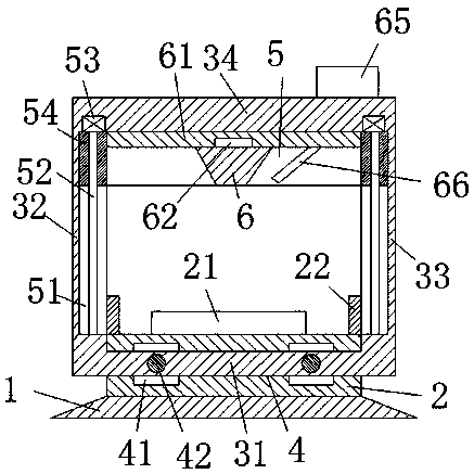
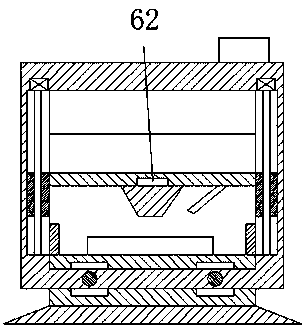
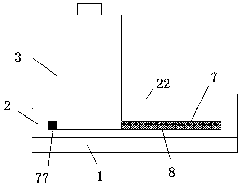
[0022] refer to Figure 1-6 A kind of building punching device shown, comprises carrier board 2 and the moving frame 3 that is connected with described carrier board 2 mobile fit, and described carrier board 2 bottom is provided with carrier 1, and described carrier board 2 is provided with The moving slot 4 that communicates with the left and right, the moving frame 3 includes a bottom horizontal plate 31 that is moved and connected with the moving slot 4, and is arranged on the left end of the bottom horizontal plate 31 and is connected with the left end surface of the carrier plate 2 for moving and fitting The left vertical plate 32, and the r...


PUM


Abstract

The invention discloses a punching device for building. The a punching device for building comprises a loading plate and a movable frame connected with the loading plate in a moving fit mode; the bottom of the loading plate is provided with a loading seat, and a left-right intercommunicating movable groove is formed in the loading plate; and the movable frame comprises a bottom transverse plate, aleft vertical plate and a right vertical plate, wherein the bottom transverse plate is connected with the movable groove in a moving fit mode, the left vertical plate is arranged at the left end of the bottom transverse plate and connected with the left end face of the loading plate in a moving fit mode, and the right vertical plate is arranged at the right end of the bottom transverse plate andconnected with the right end face of the loading plate in a moving fit mode. According to the punching device for building, the overall structure is simple, the production cost is low, the front-backposition of a drill bit is power-driven by working of a first motor, and the up-down position of the drill bit is power-driven by working of a second motor, so that the punching precision and punchingefficiency of a building decorative plate are ensured, uniformity of spacing between punched holes is ensured, operation is very convenient, and the punching device for building is suitable for usingand popularizing.

Description

technical field [0001] The invention relates to the construction field, in particular to a building punching device for punching holes in a building decorative board. Background technique [0002] Building decorative board is a kind of building decoration material, which is widely used. The building decorative board needs to be punched before use, so as to meet the fixed use of the existing decoration. The existing building decorative board is mainly punched manually. Hand-held small drilling machines are used to punch holes in architectural decorative panels. However, the efficiency of manual drilling is low, the precision of the drilled holes is low, and the drilling operation is relatively difficult. It is not suitable for drilling a large number of continuous architectural decorative panels The dust generated during manual drilling will fly around, not only pollute the air, but also affect people's health after being inhaled by the human body. Contents of the invention...

Claims


Application Information

Patent Timeline
Patent Type & Authority Applications(China)
IPC IPC(8): B23B41/00B23B47/18B23Q1/26B23Q11/00B23Q11/08
CPCB23B41/00B23Q1/26B23Q5/34B23Q11/0046B23Q11/0816
Inventor 肖信旭何建龙
Owner 广西南宁旭兆建筑工程技术有限公司
Why Eureka
Try Eureka