Supercharge Your Innovation With Domain-Expert AI Agents!

Steel pipe cutting and unloading device

A technology of cutting device and pushing device, which is applied in the direction of pipe shearing device, shearing device, shearing machine equipment, etc., can solve the problem that workpiece cutting is easy to be damaged, and achieve rationality of guarantee, reasonable design of overall structure, and prevention of damage damage effect

Inactive Publication Date: 2018-03-27
徐州润田农业机械有限公司
View PDF0 Cites 5 Cited by
  • Summary
  • Abstract
  • Description
  • Claims
  • Application Information

AI Technical Summary

Problems solved by technology

[0003] In order to overcome the deficiencies of the above-mentioned prior art, the present invention provides a steel pipe cutting and blanking device to solve the problem that workpiece blanking is easily damaged in the prior art

Method used


Image

  • Steel pipe cutting and unloading device
  • Steel pipe cutting and unloading device

Examples


Embodiment Construction

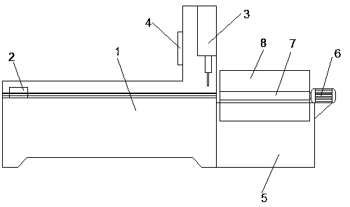
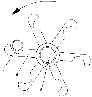
[0016] Below in conjunction with specific embodiment, content of the present invention is described in further detail: as Figure 1-2 As shown, a steel pipe cutting and blanking device includes a workbench 1, a pushing device 2 and a cutting device 3 arranged on the workbench 1, wherein the side of the workbench 1 close to the cutting device 3 has a material receiving device , the material receiving device includes a material box 5, a motor 6 fixed on the material box 5, a rotating shaft 7 connected to the motor 6, and some material receiving plates 8 evenly arranged on the rotating shaft 7; the central axis of the rotating shaft 7 is arranged along the horizontal direction, The direction of the long axis of the material receiving plate 8 is parallel to the direction of the central axis of the rotating shaft 7 , and a groove 9 is formed on the end surface of the side opposite to the direction of rotation.

[0017] As a further optimization of this embodiment, the height of the...


PUM


Abstract

The invention discloses a steel pipe cutting and blanking device, which comprises a workbench, a material pushing device and a cutting device arranged on the workbench. The side of the workbench close to the cutting device has a material receiving device. The feeding device includes a material box, a motor fixed on the material box, a rotating shaft connected to the motor, and several material receiving plates evenly arranged on the rotating shaft; the central axis of the rotating shaft is arranged along the horizontal direction, and the long axis direction of the material receiving plate Parallel to the direction of the central axis of the rotating shaft, there is a groove on the end face opposite to the rotating direction. The present invention adds a material receiving device to the traditional structure, which is used to receive the steel pipe to be cut, and make it fall smoothly into the material box, so as to prevent the structure of the steel pipe from being damaged, and the overall structure design is very reasonable.

Description

technical field [0001] The invention relates to a blanking device, in particular to a steel pipe cutting blanking device. Background technique [0002] The use of steel pipes is very wide, and according to the different requirements of use, the required length is also different, so a cutting device is required, but the current cutting device has some disadvantages. First, when the cutting device has not completely separated the steel pipes, The steel pipe will be bent downward under the influence of its own gravity, which seriously affects the flatness of the end of the steel pipe; secondly, when the steel pipe falls into the material box after cutting, one end will fall first, and the other end will fall later. If it falls, the end will directly hit other steel pipes in the material box. For some steel pipes with high surface quality requirements, the dropped steel pipes will seriously affect their quality. Therefore, the present invention develops a steel pipe cutting and ...

Claims


Application Information

Patent Timeline
IPC IPC(8): B23D21/00B23Q7/00
CPCB23D21/00B23Q7/00
Inventor 胡道安
Owner 徐州润田农业机械有限公司
Features
  • R&D
  • Intellectual Property
  • Life Sciences
  • Materials
  • Tech Scout
  • Unparalleled Data Quality
  • Higher Quality Content
  • 60% Fewer Hallucinations
Learn More