Connecting device for cab and car frame

A connecting device and cab technology, which is applied to the upper structure of trucks, vehicle parts, transportation and packaging, etc., can solve the problems of complex structure of Y-direction stabilizing mechanism, occupying a large space, and arranging many parts, and achieve the overall Effects of weight and cost control, small footprint, and guaranteed stability

Inactive Publication Date: 2018-03-27
ANHUI JIANGHUAI AUTOMOBILE GRP CORP LTD
7 Cites 0 Cited by

AI-Extracted Technical Summary

Problems solved by technology

[0004] Such setting makes the spring shock absorber rotate axially along the suspension ring, and the stability of the cab relative to the Y-direction (left-right direction) support of the vehicle frame cannot be realized. In practical applications, an additional Y-direction stabilizati...

Method used

Wherein, spring shock absorber 3 can be air spring shock absorber 3 etc., there is gap between spring shock absorber 3 and installation cylinder 4, but gap is very little, makes spring vibration absorber 3 and described installation cylinder 4 can move up and down relative to each other, but there is almost no space for relative movement in the Y direction (horizontal left and right directions). Therefore, the spring damper 3 arranged vertically is fitted with the mounting cylinder 4 in clearance, and the spring damper 3 and the The installation tubes 4 can move up and down relative to each other, and the top of the spring damper 3 is fixedly connected to the floor sheet metal 1 of the cab through the first installation frame 21, and the installation tube 4 is fixed to the vehicle frame 6 through the second installation frame 5 connection, so as to realize the restriction of the relative movement of the cab relative to the vehic...

Abstract

The invention discloses a connecting device for a cab and a car frame. The connecting device comprises a first mounting frame, a spring shock absorber, a second mounting frame and a mounting barrel. Avertically arranged spring shock absorber is in clearance fit with the mounting barrel, the spring shock absorber and the mounting barrel can relatively move up and down, the top of the spring shockabsorber is fixedly connected to the floor metal plate of the cab through the first mounting bracket, and the mounting barrel is fixedly connected with the car frame through the second mounting bracket, so the relative movement of the cab in the Y direction (horizontal right-to-left direction) of the car frame is limited so as to ensure the stability of the support in this direction. Meanwhile thespring shock absorber and the mounting barrel can relatively move up and down so that the connecting device achieves upper and lower vibration-reducing movement of the cab relative to the car frame.The connecting device has simple structure and small occupied space, and does not interfere with the arrangement of other components, so the overall weight and cost of the car can be effectively controlled.

Application Domain

Loading-carrying vehicle superstructures

Technology Topic

Vehicle frameEngineering +1

Image

  • Connecting device for cab and car frame
  • Connecting device for cab and car frame

Examples

  • Experimental program(1)

Example Embodiment

[0024] The embodiments described below with reference to the accompanying drawings are exemplary, and are only used to explain the present invention, and cannot be construed as limiting the present invention.
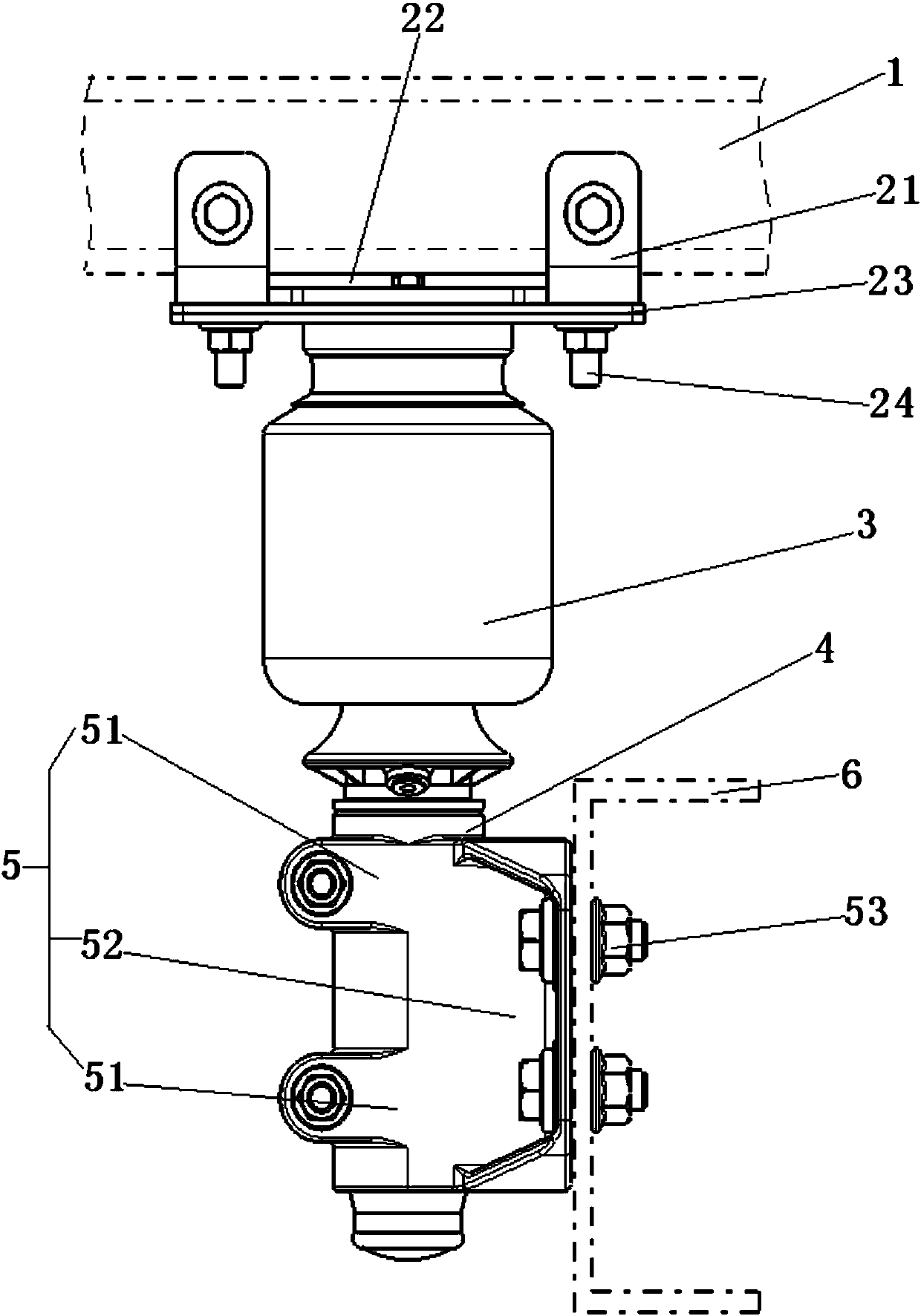
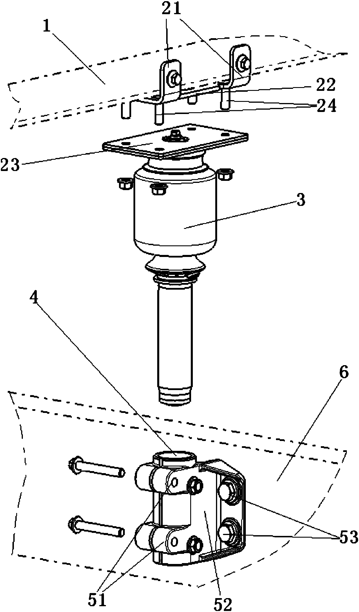
[0025] Such as figure 1 Shown, see also figure 2 , The embodiment of the present invention provides a device for connecting a cab and a frame, which includes a first mounting frame 21, a spring damper 3, a second mounting frame 5, and a mounting tube 4, and the first mounting frame 21 is fixed on On the floor sheet metal 1 of the cab, the spring damper 3 is vertically arranged, the spring damper 3 is located below the floor sheet metal 1, and the top of the spring damper 3 is fixedly connected to the first mounting frame 21 , The second mounting frame 5 is fixedly connected to the frame 6, the mounting tube 4 is vertically fixed on the second mounting frame 5, the lower part of the spring damper 3 extends into the mounting tube 4, and the spring damper 3 The lower part is in clearance fit with the mounting cylinder 4, and the spring damper 3 and the mounting cylinder 4 can move up and down relatively. Preferably, the lower part of the spring damper 3 and the mounting cylinder 4 are movably connected.
[0026] Among them, the spring damper 3 can be an air spring damper 3, etc. There is a gap between the spring damper 3 and the mounting cylinder 4, but the gap is small, so that the spring damper 3 and the mounting cylinder 4 It can move up and down relatively, but there is almost no space for relative movement in the Y direction (horizontal left and right directions). Therefore, the vertical spring damper 3 is in clearance fit with the mounting cylinder 4, and the spring damper 3 and the mounting cylinder 4 The top of the spring shock absorber 3 is fixedly connected to the floor sheet metal 1 of the cab through the first mounting frame 21, and the mounting cylinder 4 is fixedly connected to the frame 6 through the second mounting frame 5, thereby Realize the restriction of the relative movement of the cab relative to the frame 6Y (horizontal left and right directions), that is, the stability of the support in this direction is ensured. At the same time, the present invention also allows the relative up and down movement between the spring damper 3 and the mounting cylinder 4 Therefore, the upper and lower relative vibration reduction movement of the cab relative to the frame 6 is realized; and the present invention has a simple structure, a small space occupation, and does not hinder the arrangement of other components, so that the overall weight and cost of the automobile can be effectively controlled.
[0027] Preferably, the second mounting frame 5 includes two clamp parts 51 and a mounting seat 52, the mounting seat 52 is fixedly connected to the frame 6, and the two clamp parts 51 are fixed in parallel from top to bottom in order. One side of the seat 52, and the axes of the two clamp parts 51 are located on the same vertical line, the two clamp parts 51 are connected to each other, and the mounting cylinder 4 is arranged in the two clamp parts 51. Wherein, the two clamp parts 51 can be a whole, the mounting cylinder 4 is arranged in the two clamp parts 51, the interface of the clamp part 51 is fastened by bolts, and the clamp part 51 is connected to the mounting cylinder 4 by bolts. The clamping tightness can be flexibly controlled.
[0028] Preferably, the mounting seat 52 is vertically arranged, and the mounting seat 52 and the frame 6 are fixedly connected by a first fastening bolt 53 arranged horizontally. The mounting base 52 is generally a vertical mounting plate, one side and the frame 6 are fixedly connected by a first fastening bolt 53 arranged horizontally, and the other side is respectively installed with two clamp parts 51 up and down.
[0029] Preferably, the connecting device further includes a horizontally arranged fixing plate 23, the fixing plate 23 is arranged between the first mounting frame 21 and the spring damper 3, the first mounting frame 21 and the fixing plate 23, the spring damping The top of the device 3 is connected sequentially.
[0030] Preferably, the first mounting frame 21 includes an L-shaped bracket, the first end of the L-shaped bracket is connected to the side of the floor sheet metal 1, and the second end of the L-shaped bracket is bent to extend to the floor sheet metal The bottom of 1 is parallel to the floor sheet metal 1, and the second end of the L-shaped bracket is connected to the fixed plate 23 and the top of the spring damper 3 in sequence.
[0031] Preferably, there are two L-shaped brackets, and the two L-shaped brackets are connected by a connecting plate 22. The connecting plate 22 serves to strengthen the strength.
[0032] Preferably, the connecting device further includes a second fastening bolt 24, the head of the second fastening bolt 24 is located between the second end of the L-shaped bracket and the floor sheet metal 1, and the rod of the second fastening bolt 24 The part passes through the second end of the L-shaped bracket and the fixing plate 23 sequentially, and is connected by a nut.
[0033] Preferably, the connecting device further includes a buffer sleeve, and the buffer sleeve is arranged between the mounting cylinder 4 and the second mounting frame 5. The arrangement of the buffer sleeve can avoid damage to the mounting cylinder 4 and the second mounting frame 5.
[0034] The structure, features, and effects of the present invention are described in detail above based on the embodiments shown in the drawings. The above descriptions are only preferred embodiments of the present invention, but the present invention does not limit the scope of implementation as shown in the drawings. Any changes made to the concept of the present invention, or equivalent embodiments modified into equivalent changes, which still do not exceed the spirit covered by the description and the drawings, should fall within the protection scope of the present invention.

PUM

no PUM

Description & Claims & Application Information

We can also present the details of the Description, Claims and Application information to help users get a comprehensive understanding of the technical details of the patent, such as background art, summary of invention, brief description of drawings, description of embodiments, and other original content. On the other hand, users can also determine the specific scope of protection of the technology through the list of claims; as well as understand the changes in the life cycle of the technology with the presentation of the patent timeline. Login to view more.

Similar technology patents

Turning gradient control valve

InactiveCN102410270ASmooth oil flow switchingGuaranteed stability
Owner:LANZHOU UNIVERSITY OF TECHNOLOGY

Pixel circuit and driving method thereof, electroluminescent display panel and display device

ActiveCN108335668AAvoid voltage instabilityGuaranteed stability
Owner:HEFEI XINSHENG OPTOELECTRONICS TECH CO LTD +1

Classification and recommendation of technical efficacy words

  • Simple structure
  • Guaranteed stability

Sharing system for air-conditioning coat

InactiveCN107440179ASimple structureeasy to wear
Owner:QINGDAO HAIER AIR CONDITIONER GENERAL CORP LTD

Feeding device of sorter of batteries plate

InactiveCN101357717ASimple structurecooperate well
Owner:NANJING NORMAL UNIVERSITY

Emergency parachuting device and method for multiple-rotor unmanned aerial vehicle

InactiveCN103895870Aavoid aircraft crashSimple structure
Owner:SOUTH CHINA AGRI UNIV +1

A ccd-type colloidal gold immunochromatographic diagnostic test paper quantitative analysis system

InactiveCN102279263AGuaranteed stabilityAddressing Subjective Bias
Owner:杭州顿力医疗器械有限公司

General clamp for abrasive flow polishing of complicated hole surface

InactiveCN104551985AContinuous and stable flowGuaranteed stability
Owner:CHANGCHUN UNIV OF SCI & TECH

Laminated intelligent shock-isolation bearing capable of self-adaptively regulating cutting performance

InactiveCN101586641AGuaranteed stabilityThe interlayer displacement of the isolation layer is small
Owner:WUHAN UNIV OF TECH
Why Eureka
Try Eureka