Hydraulic end assembly and plunger pump with same

A liquid end and plunger pump technology, which is applied to parts of pumping devices for elastic fluids, pump elements, variable displacement pump parts, etc., and can solve the problem of disassembly and assembly of liquid end assemblies and inconvenience in maintenance, etc. problems, to achieve the effect of optimizing space layout, increasing flow channels and volumetric efficiency, and improving performance

Inactive Publication Date: 2018-03-27
BEIJING TIANMA INTELLIGENT CONTROL TECH CO LTD +1
View PDF5 Cites 5 Cited by
  • Summary
  • Abstract
  • Description
  • Claims
  • Application Information

AI Technical Summary

Problems solved by technology

[0005] In view of this, the object of the present invention is to propose a fluid end assembly and a plunger pump including it, which solves the problems of disassembly, maintenance, and maintenance inconvenience of the existing fluid end assembly, and at the same time improves the flow rate and volumetric efficiency , improve the performance of the liquid end assembly and the plunger pump, and meet the use requirements under complex working conditions

Method used


Image

  • Hydraulic end assembly and plunger pump with same

Examples


Embodiment Construction

[0030] In order to make the object, technical solution and advantages of the present invention clearer, the present invention will be described in further detail below in conjunction with specific embodiments and with reference to the accompanying drawings. Wherein the same components are denoted by the same reference numerals. It should be noted that the words "front", "rear", "left", "right", "upper" and "lower" used in the following description refer to directions in the drawings. The terms "inner" and "outer" are used to refer to directions toward or away from, respectively, the geometric center of a particular component.

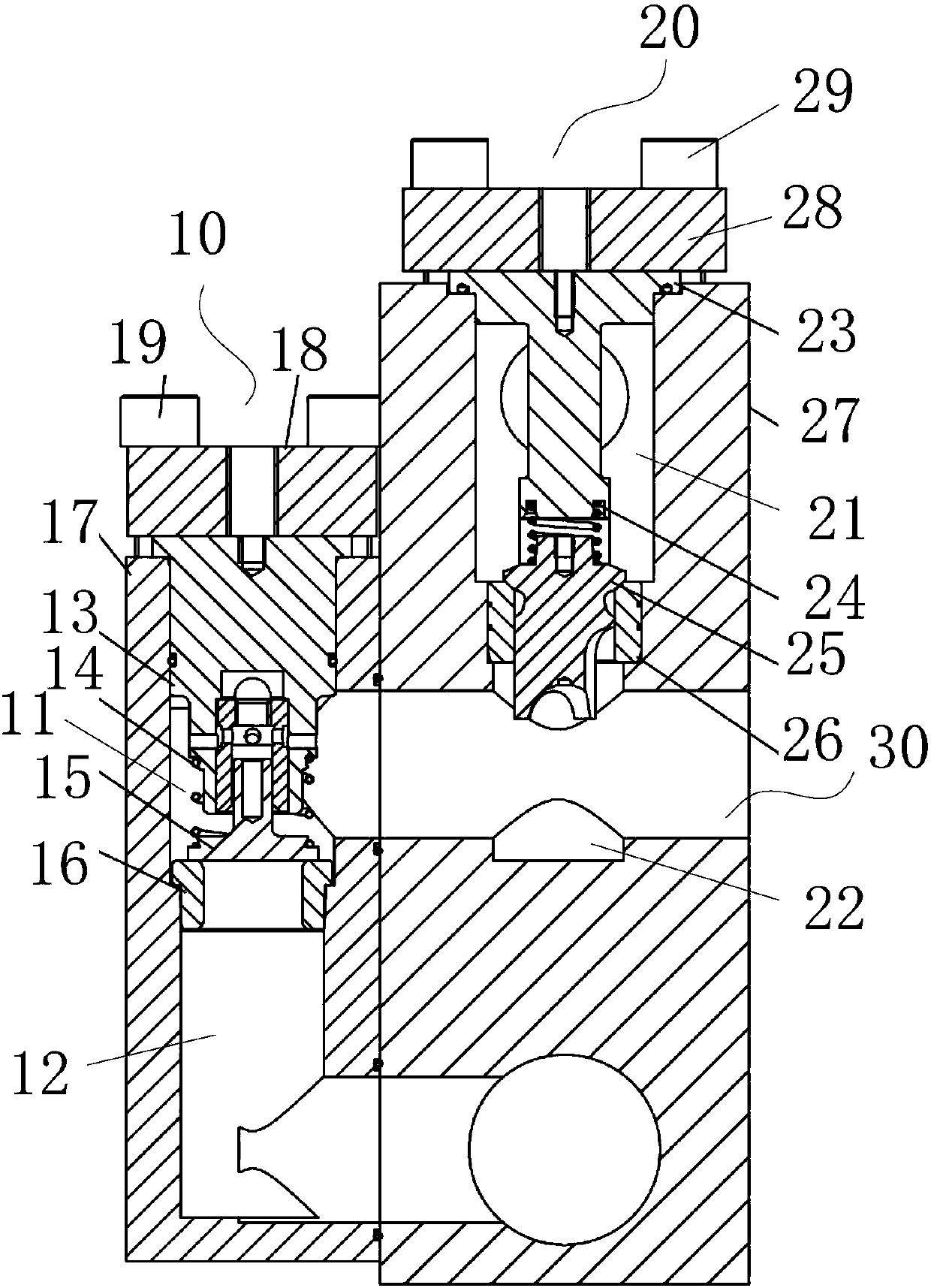
[0031] figure 1 It is a schematic diagram of the liquid end assembly used in the specific embodiment of the present invention. Such as figure 1 As shown, the liquid end assembly includes: a liquid suction valve 10 and a liquid discharge valve 20 .

[0032] A liquid suction valve chamber is arranged in the liquid suction valve 10, and a liquid suctio...


PUM


Abstract

The invention discloses a hydraulic end assembly and a plunger pump with the same. The hydraulic end assembly comprises a fluid suction valve and a fluid draining valve, wherein the fluid suction valve is internally provided with a fluid suction valve cavity, and a fluid suction valve element assembly is arranged in the fluid suction valve cavity; and the fluid draining valve is internally provided with a fluid draining valve cavity, and a fluid draining valve element assembly is arranged in the fluid draining valve cavity. The fluid suction valve and the fluid draining valve are arranged in parallel and are detachably connected, and the fluid suction valve cavity and the fluid draining valve cavity communicate with each other through a plunger cavity. The fluid suction valve element assembly is used for controlling the fluid suction valve cavity and the plunger cavity to be connected and disconnected for sucking fluid. The fluid draining valve element assembly is used for controllingthe fluid draining valve cavity and the plunger cavity to be connected and disconnected for draining fluid. According to the hydraulic end assembly and the plunger pump with the same, the problem thatan existing hydraulic end assembly is inconvenient to dismount, mount, maintain and repair is solved; and meanwhile, the excess flow is increased, volume efficiency is improved, the performance of the hydraulic end assembly and the plunger pump is also improved, and the using requirements under the complicated work conditions are met.

Description

technical field [0001] The present invention relates to a plunger pump, more specifically, to a liquid end assembly and a plunger pump including the same. Background technique [0002] The plunger pump is an important device in the hydraulic system. It relies on the reciprocating movement of the plunger in the plunger chamber to change the volume of the sealed working chamber to achieve liquid suction and discharge. The plunger pump includes a reduction mechanism and a fluid end assembly, which is used to convert mechanical energy into fluid pressure energy. [0003] The existing liquid end assembly includes a pump head main body, a liquid suction box, and a liquid suction valve seat support ring for connecting the pump head main body and the liquid suction box, wherein the pump head main body is provided with a liquid suction valve core, a liquid suction Valve seat, drain valve core, drain valve seat, and matching springs and sealing rings. When assembling, first, you nee...

Claims


Application Information

Patent Timeline
Patent Type & Authority Applications(China)
IPC IPC(8): F04B53/10F04B53/16F04B53/22
CPCF04B53/10F04B53/16F04B53/22
Inventor 李然韦文术叶健刘昊贾琛向虎王伟田成金付仙良何正刚王大龙刘波郭新伟宋艳亮张晶晶
Owner BEIJING TIANMA INTELLIGENT CONTROL TECH CO LTD
Why Eureka
Try Eureka