Locomotive auxiliary engine self-lubrication method and system

An automatic lubrication and locomotive technology, which is applied in the direction of engine lubrication, lubricating parts, mechanical equipment, etc., can solve the problems of unsuitable automatic lubrication of locomotive auxiliary equipment, etc., and achieve the effect of improving service life and ensuring driving safety

Pending Publication Date: 2018-03-27
株洲中车电气科技有限公司
View PDF10 Cites 9 Cited by
  • Summary
  • Abstract
  • Description
  • Claims
  • Application Information

AI Technical Summary

Problems solved by technology

Although the above-mentioned patent is an automatic oiling device, it is not suitable for the automatic lubrication of running locomotive auxiliary machines.

Method used


Image

  • Locomotive auxiliary engine self-lubrication method and system

Examples


Embodiment 1

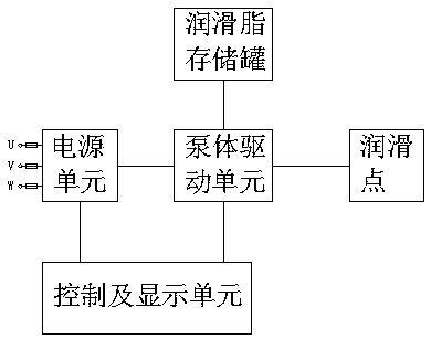
[0034] An automatic lubrication system for locomotive auxiliary equipment, including a power supply unit, a control and display unit, a pump body drive unit, and a grease storage tank, wherein the input end of the power supply unit is connected to the power supply of the locomotive auxiliary equipment, and the output end is connected to the control and display unit and the pump The control and display unit communicates with the pump body drive unit and controls the movement of the pump body drive unit, and the pump body drive unit communicates with the grease storage tank and the lubrication point of the locomotive auxiliary machine.

[0035] The input end of the power supply unit of the locomotive auxiliary machine automatic lubrication system is connected to the junction box of the locomotive auxiliary machine, and the power supply unit is used to obtain AC380V / AC440V power from the junction box, and the control and display unit controls the movement of the pump body drive uni...

Embodiment 2

[0044] The difference between this embodiment and the above-mentioned embodiments is that in this embodiment, the lubrication operation of the locomotive auxiliary equipment is completed manually, and the manual lubrication operation can be performed by setting the lubrication operation to manual mode through the operation interface.

[0045] The above-mentioned embodiment also relates to a method for automatic lubrication of locomotive auxiliary machines, which is realized through the automatic lubrication system of locomotive auxiliary machines. Obtain power and send it to each subsequent unit to make the automatic lubrication system of locomotive auxiliary equipment work. The control and display unit of the automatic lubrication system of locomotive auxiliary equipment controls the pump body drive unit to drive its plunger to suck grease from the grease storage tank and deliver the grease To the lubrication point of each auxiliary machine that needs to be lubricated.

[004...


PUM


Abstract

The invention discloses a locomotive auxiliary engine self-lubrication method and system. The method is realized through the locomotive auxiliary engine self-lubrication system and includes the stepsthat after a locomotive is started and a locomotive auxiliary engine begins to work, a power unit of the locomotive auxiliary engine self-lubrication system acquires the power from the locomotive auxiliary engine and transmits the power to all subsequent units so as to make the locomotive auxiliary engine self-lubrication system operate; and a control and display unit of the locomotive auxiliary engine self-lubrication system controls a pump body drive unit to drive a plunger to suck in lubricating grease from a lubricating grease storage tank and to convey the lubricating grease to all lubricating points needing to be lubricated of the auxiliary engine. By means of the locomotive auxiliary engine self-lubrication method and system, locomotive auxiliary fan motor bearings can be self-lubricated in timing and quantifying modes, the effect that the motor bearings are in a lubrication state all the time is guaranteed, the service life of the locomotive auxiliary fan motor bearings is prolonged, traffic safety is guaranteed, and the locomotive auxiliary engine self-lubrication method and system are suitable for self-lubrication of the auxiliary fan motor bearings of various sorts of DClocomotives and AC locomotives.

Description

technical field [0001] The invention relates to a lubricating method and system, in particular to an automatic lubricating method and system for locomotive auxiliary machines. Background technique [0002] During the operation of a railway locomotive, there are friction losses between the rail and the wheel set, between the locomotive internal gear transmission, and various motor bearings. The lubrication of these friction pairs is directly related to the wheels, rails, gears, and bearings. The life of the locomotive is related to the maintenance of the locomotive and the safety of the locomotive. Therefore, the friction, wear and lubrication of the locomotive are very important. It is necessary to ensure a good lubrication state for each friction part of the locomotive, reduce friction, reduce wear, and improve work efficiency. [0003] Such as the application number CN91229437.X, the utility model patent titled "Railway Locomotive Bearing Quantitative Oiling Machine" discl...

Claims


Application Information

Patent Timeline
Patent Type & Authority Applications(China)
IPC IPC(8): F16N7/38F16N29/00
CPCF16N7/38F16N29/00F16N2210/04F16N2210/14
Inventor 袁赞江袁理军肖劲林李少龙
Owner 株洲中车电气科技有限公司
Why Eureka
Try Eureka