
Disc-type built-in aero starter generator

A technology for starter generators and aero-engines, applied in the field of aeronautical engineering, can solve the problem of unretrieved patent documents, etc., and achieve the effects of light weight, fast response, and large magnetic flux

Inactive Publication Date: 2018-03-27
猫头鹰安防科技有限公司
View PDF5 Cites 2 Cited by
  • Summary
  • Abstract
  • Description
  • Claims
  • Application Information

AI Technical Summary

Problems solved by technology

The aviation built-in starter generator is the key technology that needs to be developed urgently at present, and no published patent documents have been retrieved in this regard

Method used


Image

  • Disc-type built-in aero starter generator
  • Disc-type built-in aero starter generator
  • Disc-type built-in aero starter generator

Examples


Embodiment 1

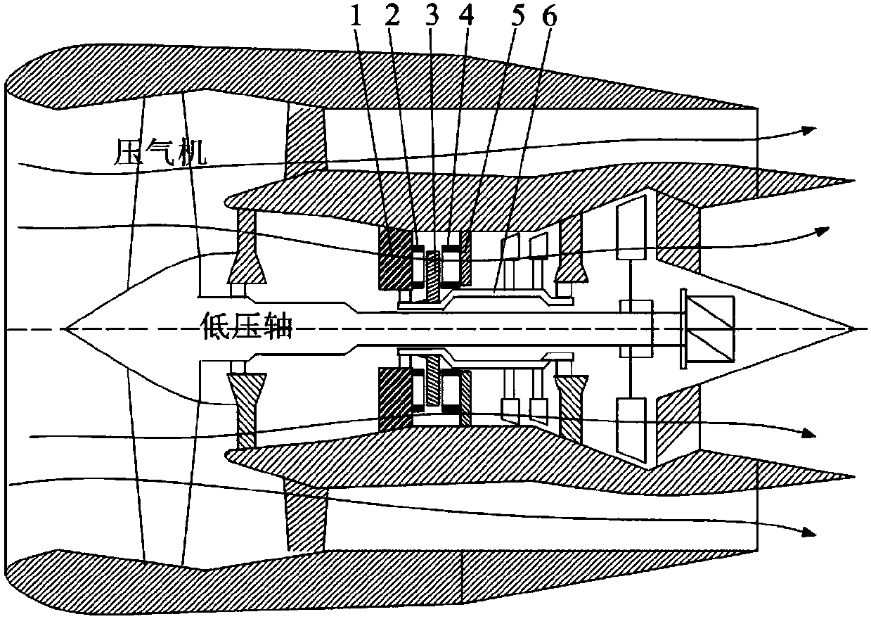
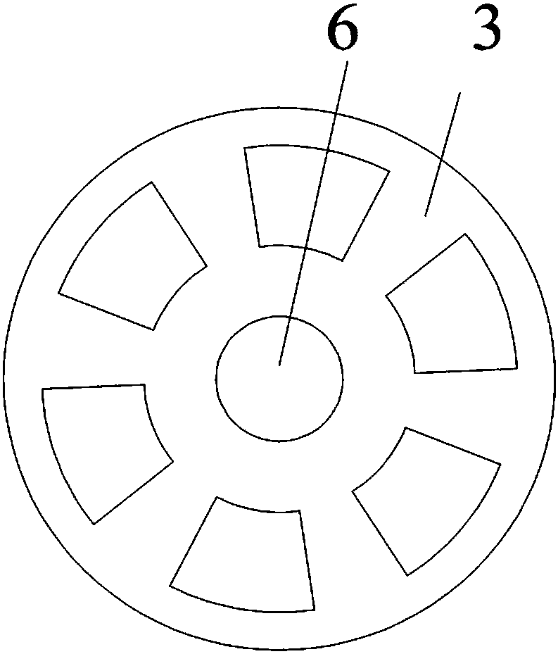
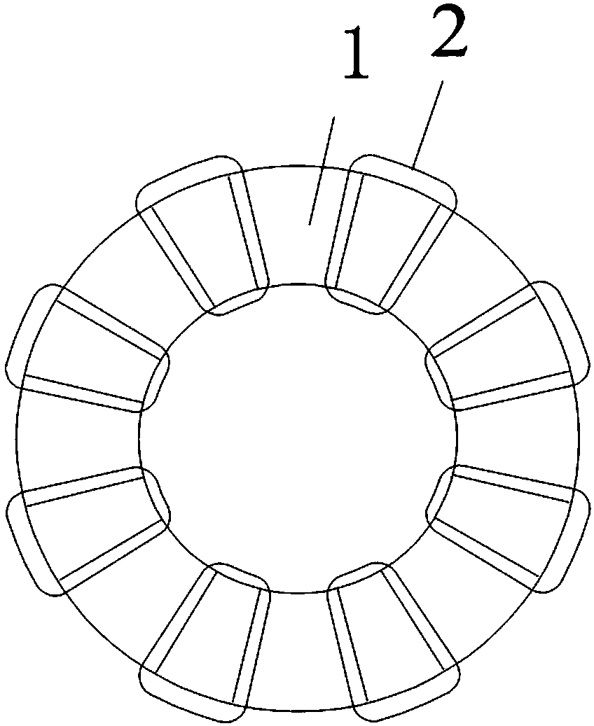
[0054] The working principle of Embodiment 1: Since the first armature core and the second armature core of the present invention are axially aligned, when the magnetically conductive part of the rotor core is aligned with the armature poles, the armature pole turn chain The reluctance of the armature turns is the smallest, and the flux linkage of the armature winding is the largest; when the fan-shaped through hole of the rotor core is aligned with the armature pole, the reluctance of the armature pole turn chain is the largest, and the flux linkage of the armature winding is the smallest.

[0055] When the magnetically conductive part of the rotor core gradually approaches the armature poles, the mutual inductance between the first armature winding and the second armature winding increases. When the magnetically conductive part of the rotor core separates from the armature poles, the self-inductance of the first armature winding and the second armature winding decreases.

[...

Embodiment 2

[0058] The working principle of embodiment two is:

[0059] Since the electric excitation magnetic poles and armature poles of the present invention are axially aligned, when the magnetically conductive part of the rotor core is aligned with the armature poles, the magnetic resistance of the armature pole turn chain is the smallest and the armature winding flux linkage is the largest ; When the fan-shaped through hole of the rotor core is aligned with the armature pole, the magnetic resistance of the armature pole turn chain is the largest, and the armature winding flux linkage is the smallest.

[0060] When the excitation winding of the motor of the present invention is energized, a magnetic field will be established inside the motor, and the generated magnetic flux will pass through the stator yoke, stator teeth, air gap, rotor teeth, and rotor yoke of each phase to form a closed loop.

[0061] In this application, the mutual inductance of the armature winding and the field ...


PUM


Abstract

The invention discloses a disc-type built-in aero starter generator, which belongs to the field of aero engineering. The disc-type built-in aero starter generator comprises a high-voltage shaft, a first stator iron core, a rotor iron core, first armature coils and a second stator iron core, and is characterized in that the rotor iron core is fixed on the high-voltage shaft of the aero engine; thefirst stator iron core and the second stator iron core with the same structures are symmetrically located at two axial sides of the rotor iron core and are fixed on the shell of the aero engine; 3k fan-shaped through holes are distributed uniformly on the circumference of the rotor iron core, and k is a positive integer larger than 1; and one side, facing the rotor iron core, of each of the firststator iron core and the second stator iron core is provided with 4k uniformly-distributed fan-shaped convex armature poles, and the armature poles of the first stator iron core are wound with integrated armature coils. The rotor iron core in the invention has small moment of inertia, and high-speed rotation can be achieved; and the rotor iron core is located on the high-voltage shaft of the engine, the rotation speed is high, the power is larger, and the disc-type built-in aero starter generator is extremely suitable for serving as an aero built-in generator.

Description

technical field [0001] The utility model relates to a disc type built-in aviation starter generator, which belongs to the field of aviation engineering. Background technique [0002] More electric aircraft and all-electric aircraft are the inevitable trend of modern aircraft development. Having a starter generator is an important feature of a multi-electric aircraft. On the basis of the traditional aviation gas turbine engine, the magnetic suspension bearing for the built-in starter generator to support the engine rotor is installed inside the aircraft engine, eliminating the need for a transmission mechanism and running at a high speed. Provide sufficient power to supply components such as distributed electronic control systems, electric fuel pumps and electric actuators. [0003] The overall industry strength of my country's engine industry started late, and the technical foundation is relatively weak. In addition, Europe and the United States have blocked China's engine ...

Claims


Application Information

Patent Timeline
Patent Type & Authority Applications(China)
IPC IPC(8): H02K16/04H02K1/14H02K1/22
CPCH02K1/14H02K1/22H02K16/04H02K2213/03
Inventor 史立伟周波韩震周鹏超王保成王俊辉李本晟
Owner 猫头鹰安防科技有限公司
Learn More