Fluidic devices with at least one actionnable fiber

A fluid and fiber technology, applied in the field of micron-scale, small-scale, nano-scale and millimeter-scale fluid systems, can solve problems such as difficult and restrictive system operation

Pending Publication Date: 2018-03-27
CENT NAT DE LA RECH SCI (C N R S) +2
View PDF18 Cites 0 Cited by
  • Summary
  • Abstract
  • Description
  • Claims
  • Application Information

AI Technical Summary

Problems solved by technology

However, the need to hold the two surfaces carrying complex regions close together without leakage is technically difficult and limits the operation of the system

Method used


Image

  • Fluidic devices with at least one actionnable fiber
  • Fluidic devices with at least one actionnable fiber
  • Fluidic devices with at least one actionnable fiber

Examples


preparation example Construction

[0717] - Preparation of removable fibers:

[0718] As noted above, the fibers of the present invention can be made from any type of material, and in fact, various types of materials that have been formed into fibers can be purchased and used. This has been demonstrated, for example, in Example 6: the movable fibers are nylon fibers, the catheters are prepared by punching with needles, and the PDMS chip already contains microchannels. The PDMS chip was fabricated by conventional soft lithography.

[0719] In some cases, however, the present invention must alter the shape of pre-existing fibers, or must construct new fibers with a predetermined shape.

[0720] In some embodiments, the present invention further comprises the step of adjusting the shape of the manipulable fiber over a portion of its length. Non-limiting means include:

[0721] A: Compresses fibers in one direction

[0722] B: locally stretch the fiber

[0723] C: Locally cast other materials on fibers

[0...

Embodiment 1

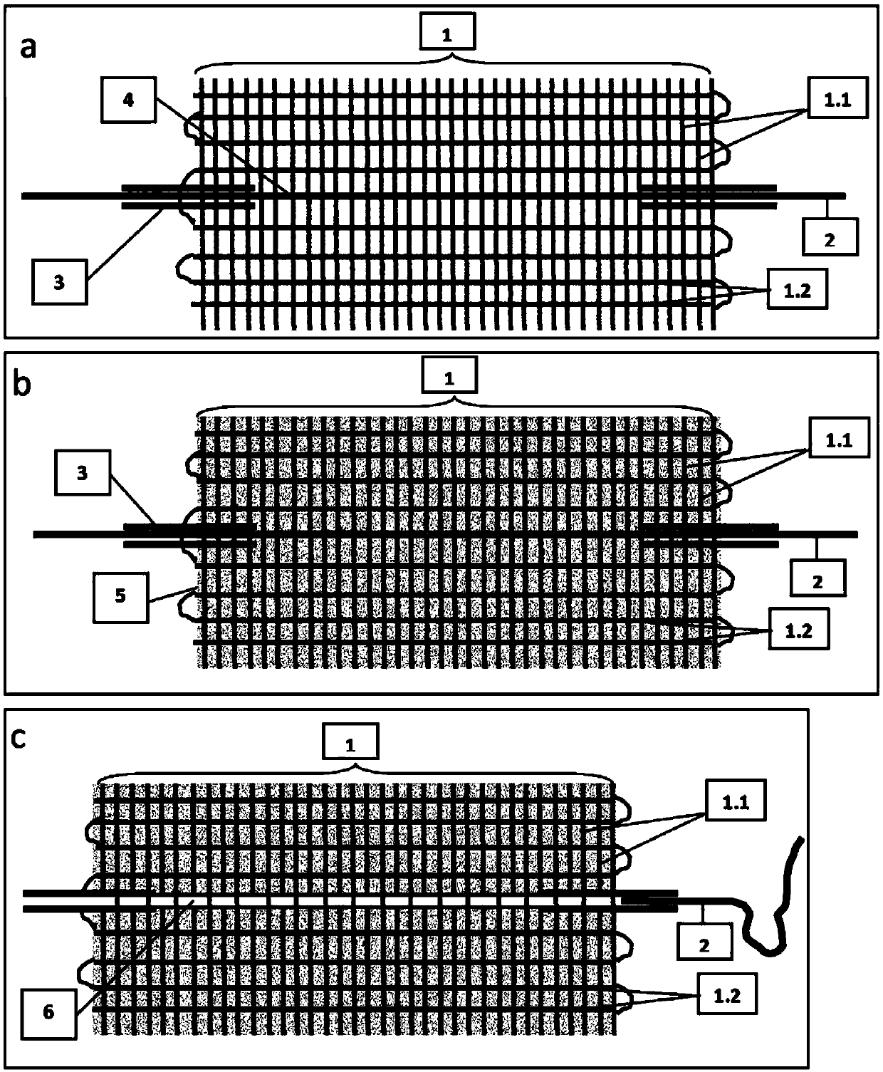
[0813] figure 1 The first example given in shows the use of a fabric support [1], one of the preparation methods for producing an inventive component or chip comprising a A single straight conduit [4] that contains movable fibers. First, a fiber fabric [1] made from support fibers [1.1] was mid-woven with a loom (Ashford, NZ). In addition to weaving, movable fibers [2] are inserted into two short silicone tubes [3], which serve as external ports in the resulting chip. Together with the tube [3], the movable fiber [2] is then added along the weft thread support fiber [1.2], by replacing a section of the weft thread fiber, to the end of half of the fabric fiber, as figure 1 As shown in a, the other half of the fabric fibers are still woven.

[0814] After weaving is completed, the fiber fabric [1] is separated from the loom and dipped into matrix precursor material [5]. Before being hardened, the matrix precursor material wicks the support fibers [1.1, 1.2], and its spatia...

Embodiment 2

[0816] Embodiment 2: the purposes of the present invention as integrated pump

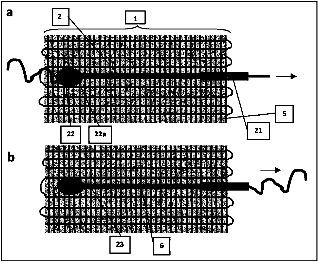
[0817] Prepare in the same manner as in Example 1 figure 2 device, except for the following two features:

[0818] First, insert only one end of the movable fiber [2] into the silicone tube [21]. During picking, the other end is partially inserted into the shed and thus protrudes from the surface of the fabric [1]. After the matrix [5] has hardened, the movable fibers [2] protrude from the matrix [5]. A drop of colored water [22a] is placed on the fabric at a location [22] where the movable fiber [2] exits the fabric and defines a fluid drop zone [22]. The movable fiber [2] is then pulled and partially removed, which allows fluid to enter the conduit [23], the space created by the fiber [2], similar to a microsyringe (see figure 2 b).

[0819] For this example, the supporting fibers of the fabric [1] were white cotton threads (n°7, Phildar, FR). The movable fiber [2] was a fluorocarbon mo...


PUM


Abstract

A minifluidic device comprising a matrix, an elongated guiding duct (109) embedded at least in part in said matrix, with at least one port to the outside of the matrix, a movable fiber (104) at leastpartly contained in said guiding duct (109), and able to undergo within said guiding duct (109), and at least along some part of said fiber (104), at least one action selected among a sliding, or a deformation, or a rotation and at least one of the movable fiber or the guiding duct is elastic or is non linear along at least part of its length, or at least part of the matrix is elastic.

Description

technical field [0001] The present invention relates to the field of miniature, microscale, nanoscale and millimeter scale fluid systems and methods of making these systems. More specifically, the present invention is directed to a fluid system comprising at least one conduit and at least one movable fiber at least partially contained within said conduit. Background technique [0002] Microfluidic devices, or more generally small fluidic devices, have advantages that conventional devices do not The accuracy that can be achieved is therefore of considerable importance. Its range of applications is increasing very rapidly. It includes without limitation diagnostics, monitoring of food quality, environmental pollution, security, forensics, chemical, physical or biological processes. Other target areas are the development of portable or wearable devices for monitoring, for people in different environments (such as the military), for scientific or humanitarian operations, for ...

Claims


Application Information

Patent Timeline
Patent Type & Authority Applications(China)
IPC IPC(8): B01L3/00F16K99/00
CPCB01L3/502707B01L3/502738B01L2300/0816B01L2300/0883B01L2400/0644B01L2400/065F16K99/0003F16K2099/0073F16K2099/0082F16K99/0011F16K99/0013F16K2099/0084
Inventor 巴斯蒂安·文扎克山田彩子珍-路易斯·维奥维斯蒂芬妮·德克鲁瓦劳伦·马拉坎
Owner CENT NAT DE LA RECH SCI (C N R S)
Why Eureka
Try Eureka