Multi-fuel engine apparatus

An internal combustion engine and multi-fuel technology, applied to combustion engines, internal combustion piston engines, mechanical equipment, etc.

Inactive Publication Date: 2018-03-27
WESTPORT POWER
View PDF9 Cites 5 Cited by
  • Summary
  • Abstract
  • Description
  • Claims
  • Application Information

AI Technical Summary

Problems solved by technology

[0006] The prior art lacks techniques for adjusting an engine from running on liquid fuel to running on liquid fuel or gaseous fuel, or both

Method used


Image

  • Multi-fuel engine apparatus
  • Multi-fuel engine apparatus
  • Multi-fuel engine apparatus

Examples


Embodiment Construction

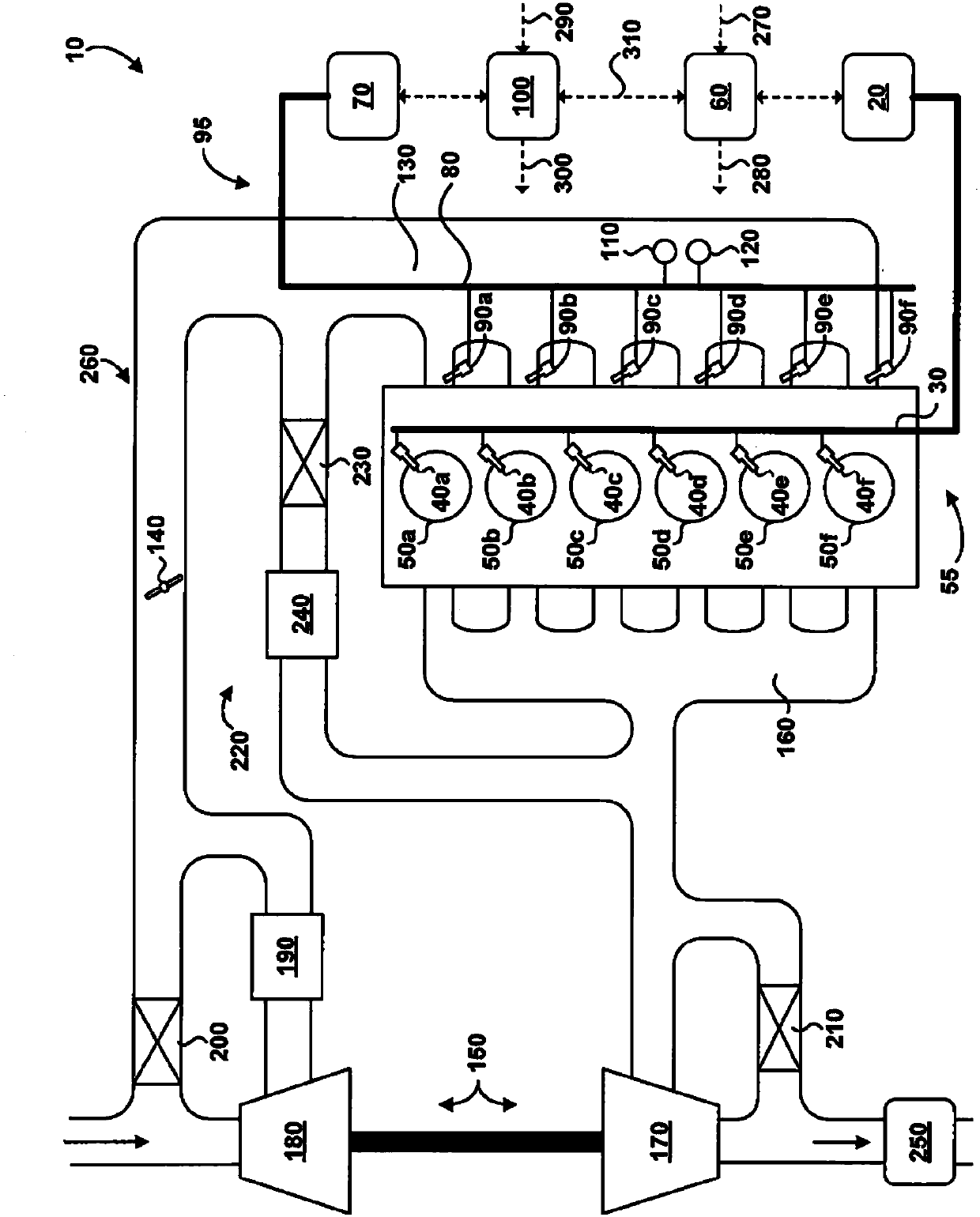
[0020] refer to figure 1is a schematic illustration of a multi-fuel engine 10 according to an embodiment in which an engine originally designed to run on liquid fuels has been adapted to additionally or alternatively run on gaseous fuels. Liquid fuel supply 20 delivers liquid fuel to liquid fuel rail 30 at a pressure suitable for post-cycle direct injection into combustion chambers 50a-50f (collectively 50a-f). Late cycle direct injection refers to the introduction of fuel directly into the combustion chamber late in the compression stroke. Alternatively or additionally, in other embodiments, liquid fuel supply 20 may deliver liquid fuel to rail 30 at a pressure suitable for early cycle direct injection. Liquid fuel injectors 40a-40f (collectively 40a-f) are in fluid communication with the liquid fuel rail, and when commanded by electronic controller 60, liquid fuel injectors 40a-40f introduce liquid fuel directly into respective combustion chambers 50a-f . Liquid fuel syst...


PUM


Abstract

It is a challenge to adapt an engine designed to be fuelled with first fuel to be fuelled with multiple types of fuel when a base engine electronic control unit cannot be adapted as well. A multi-fuelinternal combustion engine that can be fuelled with at least one of first and second fuel comprises a first fuel injector for introducing the first fuel directly into a combustion chamber; a first electronic controller programmed to generate a first injector drive signal for actuating the first fuel injector; a second fuel injector for introducing the second fuel upstream of an intake valve; a second electronic controller programmed to generate a second injector drive signal for actuating the second fuel injector; an emulation injector comprising an electrical characteristic representative ofa first fuel injector electrical characteristic; and an injector select apparatus operatively connected with the second electronic controller for selectively applying the first injector drive signalto one of the first fuel injector and the emulation injector. The second electronic controller is programmed to generate the second injector drive signal as a function of the first injector drive signal and to command the injector select apparatus to apply the first injector drive signal to one of the first fuel injector and the emulation injector.

Description

technical field [0001] The present application relates to devices for multi-fuel internal combustion engines, in particular for dual-fuel engines. Background technique [0002] A dual-fuel internal combustion engine is fueled by two different fuels and can run on a single fuel in a single pass. A typical dual fuel engine runs on a liquid fuel such as petrol (also known as gasoline) and a gaseous fuel such as compressed natural gas (CNG) or liquefied propane gas (LPG). A gasoline engine designed to be fueled by gasoline may be adjusted to operate as a dual fuel engine and may be operated in a gasoline mode, in which the engine is fueled by gasoline, or in a gaseous fuel mode The lower engine is fueled by CNG or LPG. This adjustment involves the addition of a gaseous fuel system including fuel injectors to introduce the gaseous fuel, and the means to actuate these injectors. A gaseous fuel electronic controller may be employed to actuate the gaseous fuel injectors, or a bas...

Claims


Application Information

Patent Timeline
Patent Type & Authority Applications(China)
IPC IPC(8): F02D19/06F02D41/30F02M21/02
CPCF02D19/061F02D19/0628F02D19/0647F02D19/066F02D19/0692F02D19/081F02D41/0025F02D41/0027F02D41/28F02D41/3005F02D41/3094F02D2400/11F02M26/05Y02T10/30
Inventor C·J·沃克
Owner WESTPORT POWER
Why Eureka
Try Eureka