
Method, control apparatus and vehicle

A technology for controlling equipment and transmitters, applied in transmission monitoring, transportation and packaging, instruments, etc., can solve the problems of high phase difference technology and cost, and achieve the effect of simple calculation cost

Inactive Publication Date: 2018-03-27
VOLKSWAGEN AG
View PDF5 Cites 0 Cited by
  • Summary
  • Abstract
  • Description
  • Claims
  • Application Information

AI Technical Summary

Problems solved by technology

The determination of the phase difference may require relatively high technical effort

Method used


Image

  • Method, control apparatus and vehicle
  • Method, control apparatus and vehicle
  • Method, control apparatus and vehicle

Examples


Embodiment Construction

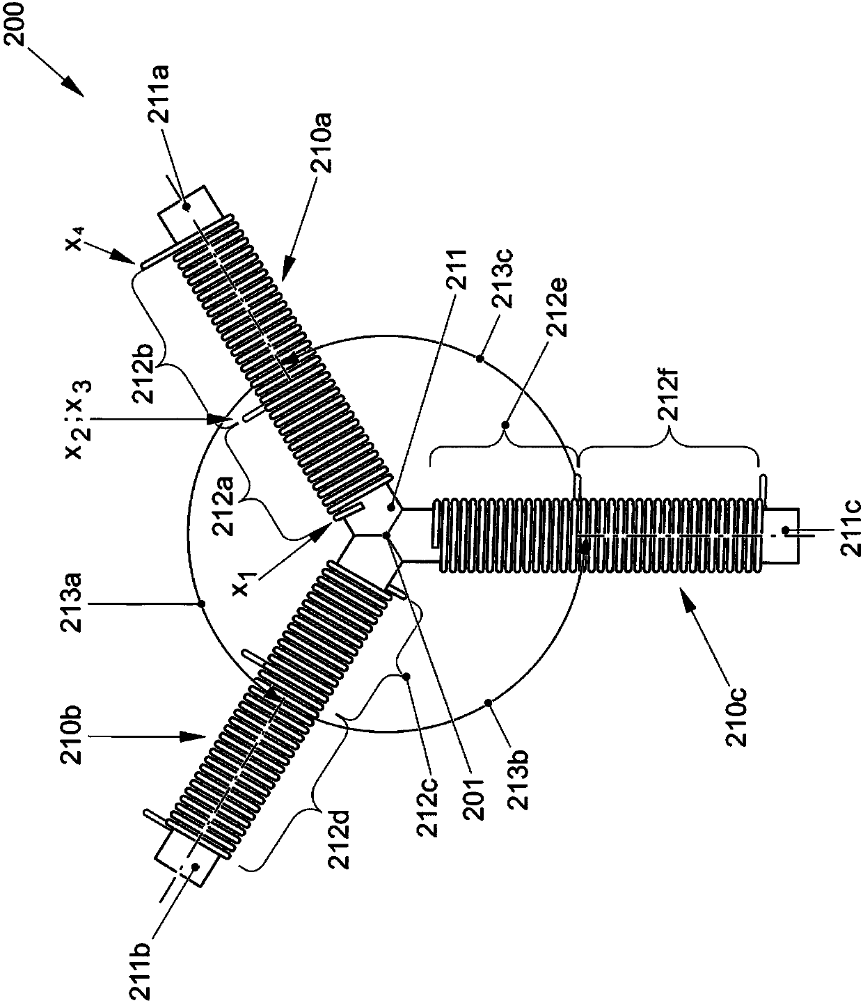
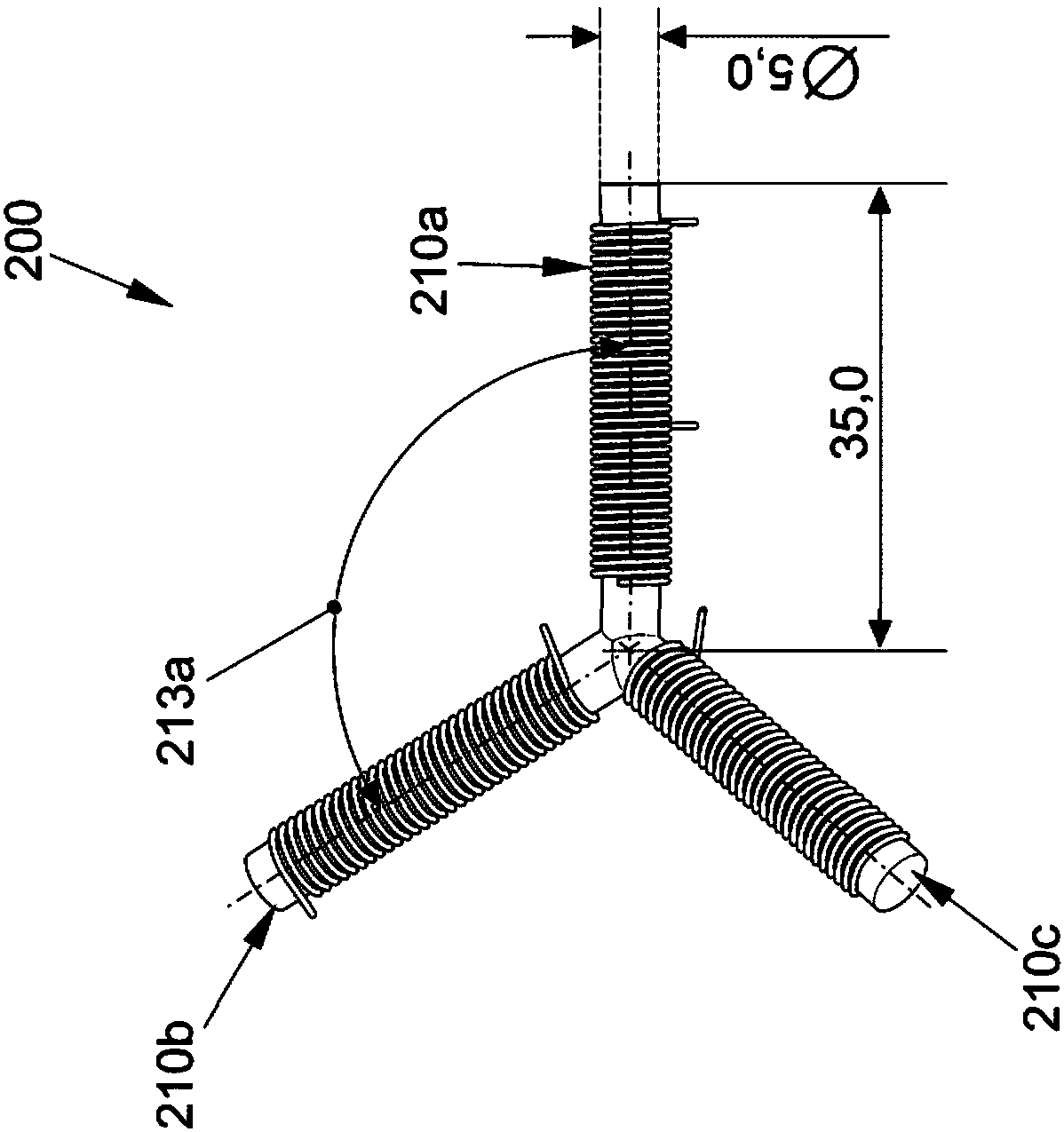
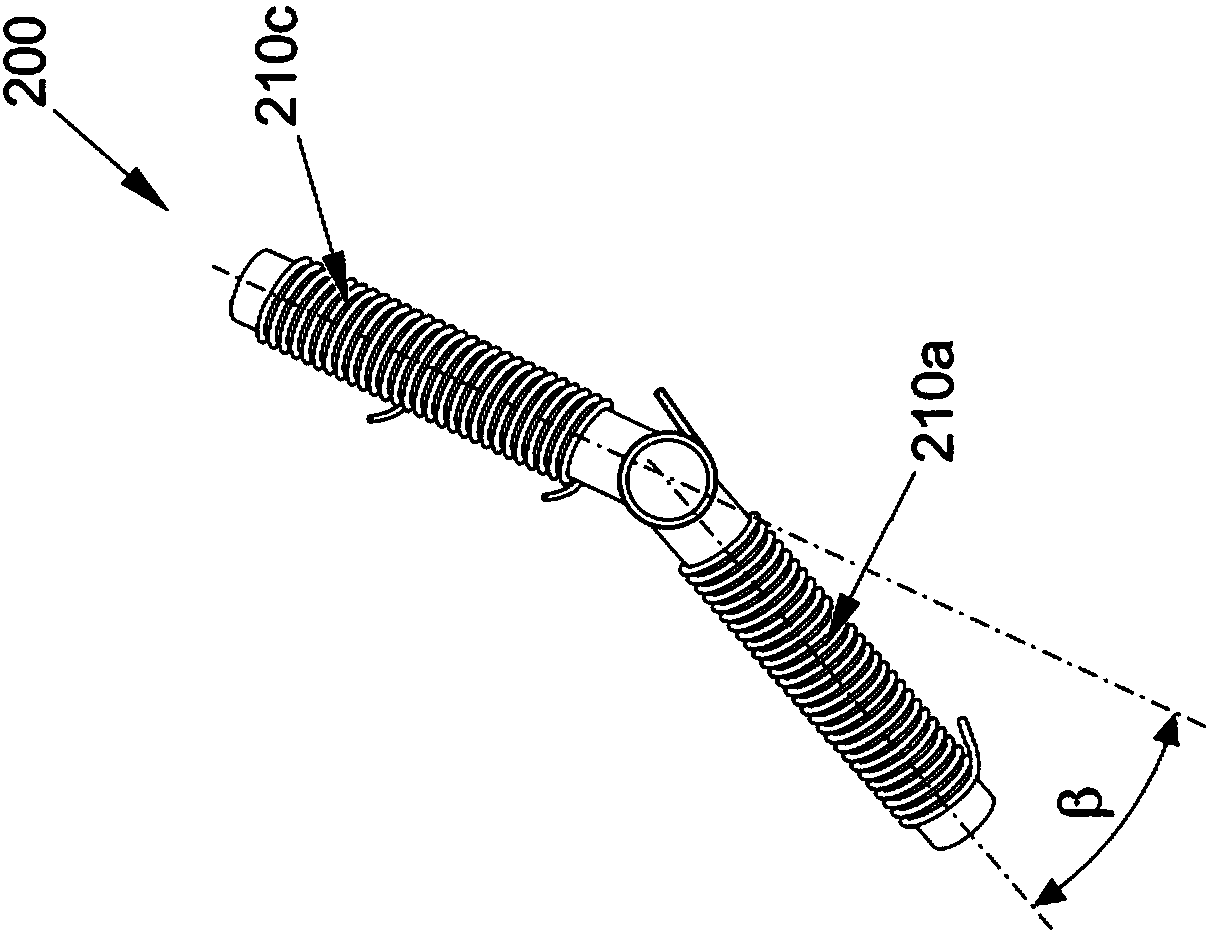
[0119] The invention is explained in detail below on the basis of preferred embodiments with reference to the drawings. In the drawings, the same reference numerals denote the same or similar elements. The drawings are schematic representations of different embodiments of the invention. Elements shown in the drawings are not necessarily shown to scale. The different elements shown in the figures are presented in such a way that their functions and general usage are readily apparent to those skilled in the art. Connections and couplings between functional units and elements shown in the figures may also be realized as indirect connections or couplings. The connection or coupling can be wired or wireless. The functional units can be realized as hardware, software or a combination of hardware and software.

[0120] The technique set forth below enables determining the angular placement of the receiver relative to the transmitter based on the amplitudes of at least two electro...


PUM


Abstract

The invention relates to a transmitter (200) which is controlled so that the transmitter (200) emits at least two electromagnetic fields. An amplitude of each of the at least two electromagnetic fields has an anisotropy in one plane. An angular arrangement (alpha) of the receiver (30) relative to the transmitter (200) is determined on the basis of the amplitude of the at least two electromagneticfields at the position of a receiver (30).

Description

technical field [0001] Various embodiments of the invention relate to methods, control devices and vehicles. The different embodiments relate in particular to techniques which enable the angular arrangement of the receivers to be determined relative to the transmitter. Background technique [0002] Technologies are known which allow localization, ie determination of position, for example by means of identification sensors. An example of an identification sensor is, for example, a key for a vehicle: technologies are thus known which allow the position of the key to be determined in the environment of the vehicle in order to enable control of entry into the vehicle. This means, for example, that the locked state of a door lid of a vehicle can be controlled. Conventional techniques here are generally based on the measurement of the field strength of the electromagnetic field emitted by the central transmitter. Since the field strength decreases with increasing distance from ...

Claims


Application Information

Patent Timeline
Patent Type & Authority Applications(China)
IPC IPC(8): G01S1/12G01B7/14G01S1/14G01S1/46G01S5/12
CPCG01S1/12G01S1/14G01S1/46G01S5/12G01S11/06G01B7/003H04B17/104B60R25/01B60R25/20H04B1/03
Inventor B.埃特R.彼得里克
Owner VOLKSWAGEN AG
Learn More