
Reverse clamping rotating workbench assembly for steering knuckle

A technology of rotary table and steering knuckle, which is used in metal processing mechanical parts, clamping, positioning devices, etc., can solve the problem that steering knuckle fixtures cannot meet the processing requirements of quick loading and unloading, the processing efficiency of steering knuckles is strict, and it is difficult to meet production requirements. and other problems to achieve the effect of optimizing the overall layout, optimizing the clamping components, and improving the efficiency

Inactive Publication Date: 2018-03-30
SUZHOU ZHENJIACHEN PRECISION MACHINERY CO LTD
View PDF10 Cites 1 Cited by
  • Summary
  • Abstract
  • Description
  • Claims
  • Application Information

AI Technical Summary

Problems solved by technology

[0002] The steering knuckle is the main part of the steering of the car, which makes the car run stably and transmits the driving direction sensitively. It is getting bigger and bigger, and the output is getting higher and higher, and the requirements for the processing efficiency of the steering knuckle are becoming more and more stringent. The table structure of ordinary machine tools has been difficult to meet the output requirements; Some steering knuckle fixtures cannot meet the processing requirements of fast loading and unloading, which is not conducive to improving processing efficiency

Method used


Image

  • Reverse clamping rotating workbench assembly for steering knuckle
  • Reverse clamping rotating workbench assembly for steering knuckle
  • Reverse clamping rotating workbench assembly for steering knuckle

Examples


Embodiment Construction

[0014] The present invention is described below in conjunction with accompanying drawing.

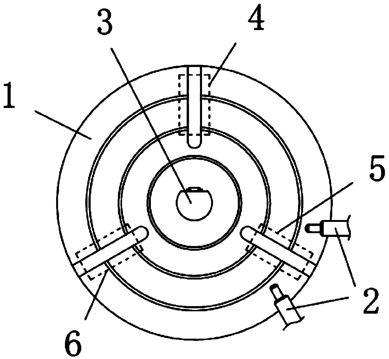
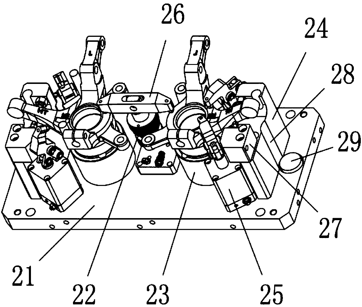
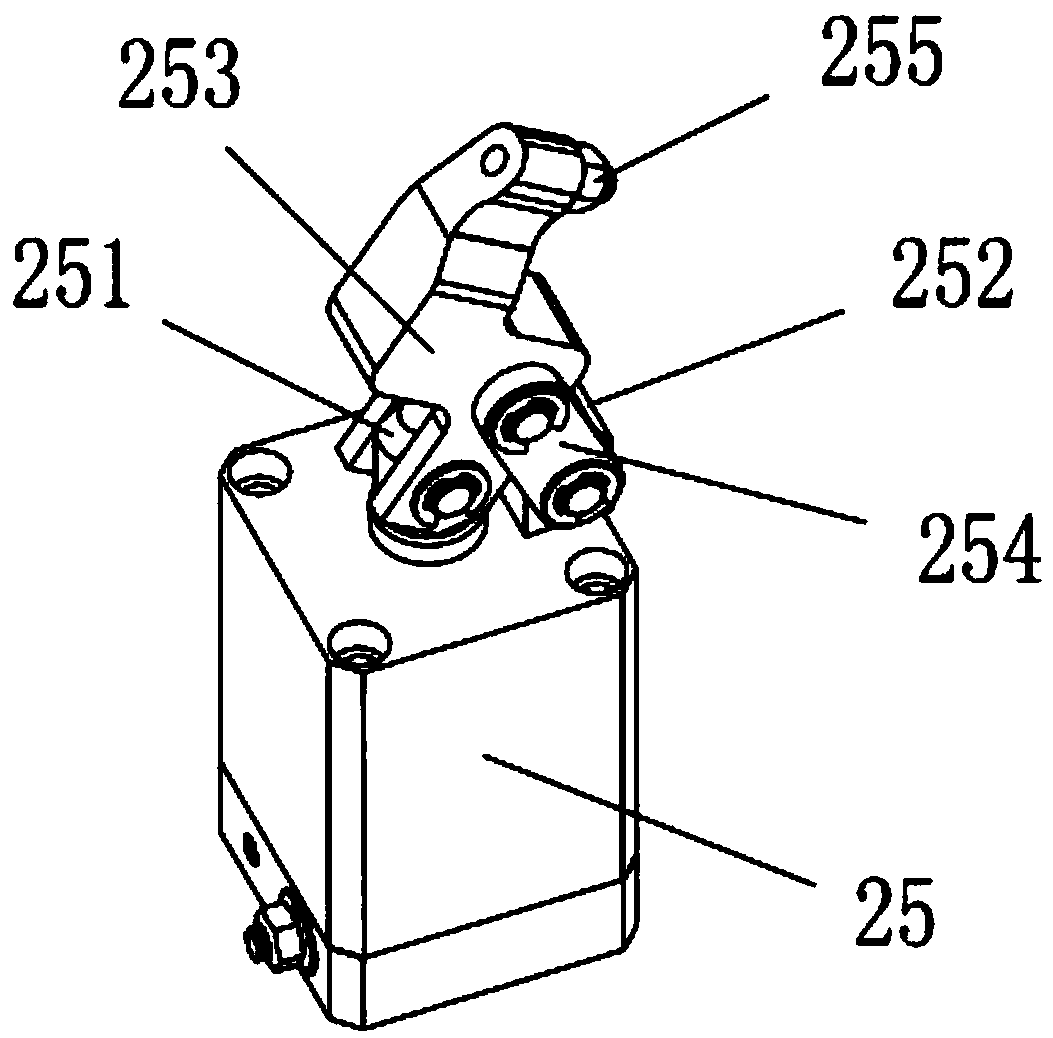
[0015] as attached Figure 1-3 As shown, a reverse clamping rotary table assembly of a steering knuckle according to the present invention includes a rotary table 1 and a flushing device 2; the rotary table 1 is a disc structure, and the center of the rotary table 1 is set There is a rotating shaft connection part 3, and the rotary table 1 is connected to the rotating drive mechanism through the rotating shaft connecting part 3; the rotary table 1 is provided with three fixture installation parts, and the three parts are respectively the processing part 4, the cleaning part 5 and the loading and unloading part 6. The working properties of the three positions are constantly changing with the rotation of the worktable, and each position is equipped with a reverse clamping fixture; the washing device 2 cooperates with the cleaning part 5, and the washing device 2 is generally connected to ...


PUM


Abstract

The invention discloses a rotating workbench assembly for a steering knuckle. The rotating workbench assembly comprises a rotating workbench and a washing device; the rotating workbench is of a disc structure and is provided with a rotating shaft connection part, a machining part, a cleaning part and an assembling and disassembling part, and each part is provided with a reverse clamping fixture; each reverse clamping fixture comprises a base, a main pressing seat and a horizontal clamping assembly is arranged on the base, the horizontal clamping assembly comprises a positioning seat, a clamping seat and two auxiliary pressing seats; and each main pressing seat is provided with a main press arm, each clamping seat is provided with a steering arm clamping block and a fixed jacking head, andeach steering arm clamping block is provided with a hydraulic jacking head. According to the reverse clamping rotating workbench assembly for the steering knuckle, the three fixture installing parts are arranged on the workbench, one fixture installing part is used for machining, the other two fixture installing parts are used for washing as well as assembling and disassembling, and the machiningefficiency is improved; in addition, clamping parts of the fixtures are optimized, the assembling and disassembling speed of the steering knuckle workpiece are increased, and the efficiency is improved; and the main body structure of the steering knuckle workpiece is fixed through all the clamping parts, and the clamping stability is ensured.

Description

technical field [0001] The invention relates to a reverse clamping rotary table assembly of a steering knuckle. Background technique [0002] The steering knuckle is the main part of the steering of the car, which makes the car run stably and transmits the driving direction sensitively. It is getting bigger and bigger, and the output is getting higher and higher, and the requirements for the processing efficiency of the steering knuckle are becoming more and more stringent. The table structure of ordinary machine tools has been difficult to meet the output requirements; Some steering knuckle fixtures cannot meet the processing requirements of fast loading and unloading, which is not conducive to improving processing efficiency. Contents of the invention [0003] In view of the above-mentioned technical problems, the purpose of the present invention is to propose a reverse clamping rotary table assembly of the steering knuckle. [0004] The technical solution of the prese...

Claims


Application Information

Patent Timeline
Patent Type & Authority Applications(China)
IPC IPC(8): B23Q1/25B23Q3/08B23Q11/00
CPCB23Q1/25B23Q3/082B23Q11/00
Inventor 黄晨
Owner SUZHOU ZHENJIACHEN PRECISION MACHINERY CO LTD
Learn More