Precast beam wet joint diaphragm plate variable space operation platform and manufacturing method thereof

A technology of working platform and variable space, which is applied in the direction of bridges, bridge construction, erection/assembly of bridges, etc. It can solve the problems of difficulty in guaranteeing construction quality, difficulty in supporting and erecting, and high construction costs, so as to ensure the squareness of the bottom space and prevent falling The bottom space is square and easy to move

Pending Publication Date: 2018-03-30
CHINA CONSTR FIRST GROUP THE FIFTH CONSTR +1
0 Cites 0 Cited by

AI-Extracted Technical Summary

Problems solved by technology

[0005] The purpose of the present invention is to provide a prefabricated beam wet joint diaphragm variable space operating platform and its manufacturing method, to solve the difficulty of erecting temporary supports ...

Method used

Step 4: Utilize the crotch on the horizontal steel bar and the crotch on the vertical steel bar to adjust the size of the space, and record the hooking position, which is conducive to the initial stage of assem...

Abstract

A prefabricated beam wet joint diaphragm variable space operating platform and its manufacturing method, wherein the operating platform is set at the joint position of two adjacent prefabricated beams, including a bottom plate structure, an enclosure structure and a connecting member; The bottom plate structure is horizontally arranged at the bottom of the work platform; the enclosure structure is arranged along the edge of the bottom plate structure, and together with the bottom plate structure forms a box-shaped structure with a bottom and no cover; the connecting members are respectively arranged in the enclosure Both sides of the top of the protective structure; the width of the two connecting members is smaller than the width of the wet joint to be constructed; the bottom edge of the connecting member is hingedly connected with the top edge of the enclosure structure, and the top edge of each connecting member passes through The pre-embedded reinforcement gap in the wet joint to be constructed is detachably connected to the fixed member above the top surface of the prefabricated beam. The invention solves the technical problems of difficulty in setting up temporary supports at the lower part in traditional prefabricated beam joint construction, high construction cost, dangerous operation, low work efficiency and difficulty in guaranteeing construction quality.

Application Domain

Bridge erection/assembly

Technology Topic

Quality assuranceJoint variable +2

Image

  • Precast beam wet joint diaphragm plate variable space operation platform and manufacturing method thereof
  • Precast beam wet joint diaphragm plate variable space operation platform and manufacturing method thereof
  • Precast beam wet joint diaphragm plate variable space operation platform and manufacturing method thereof

Examples

  • Experimental program(1)

Example Embodiment

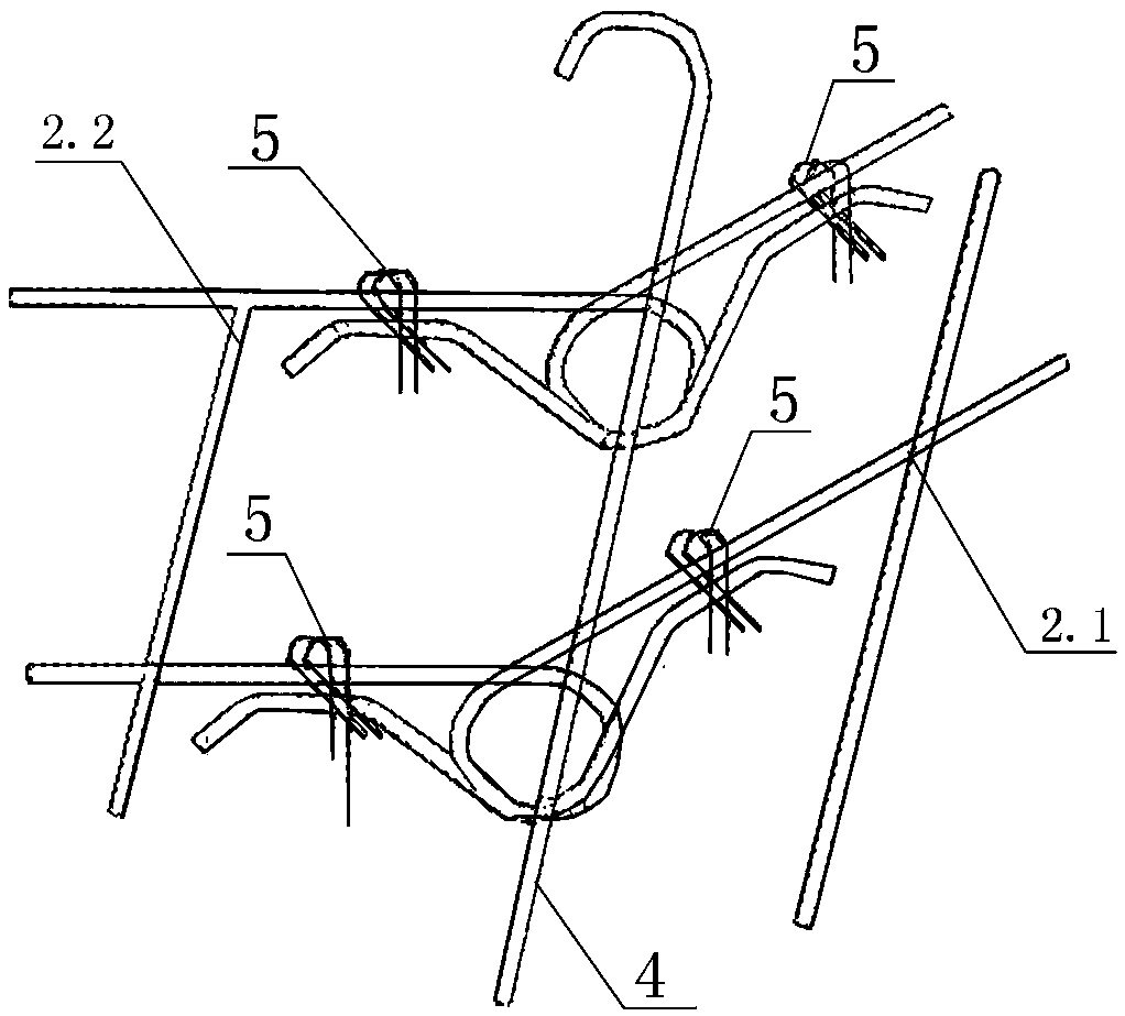
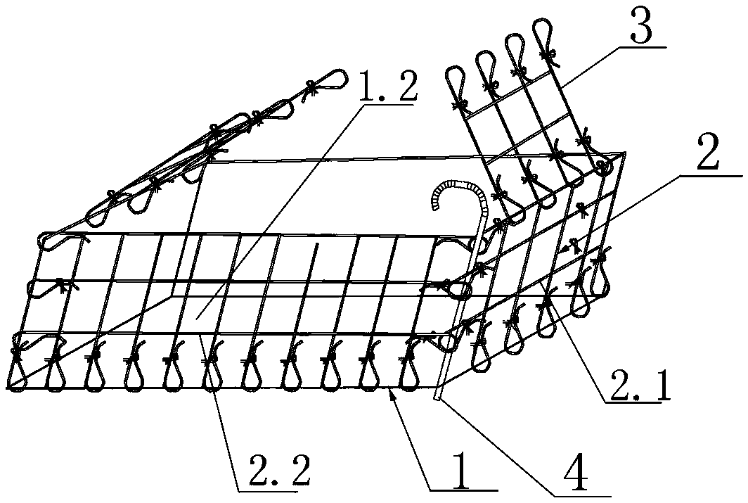
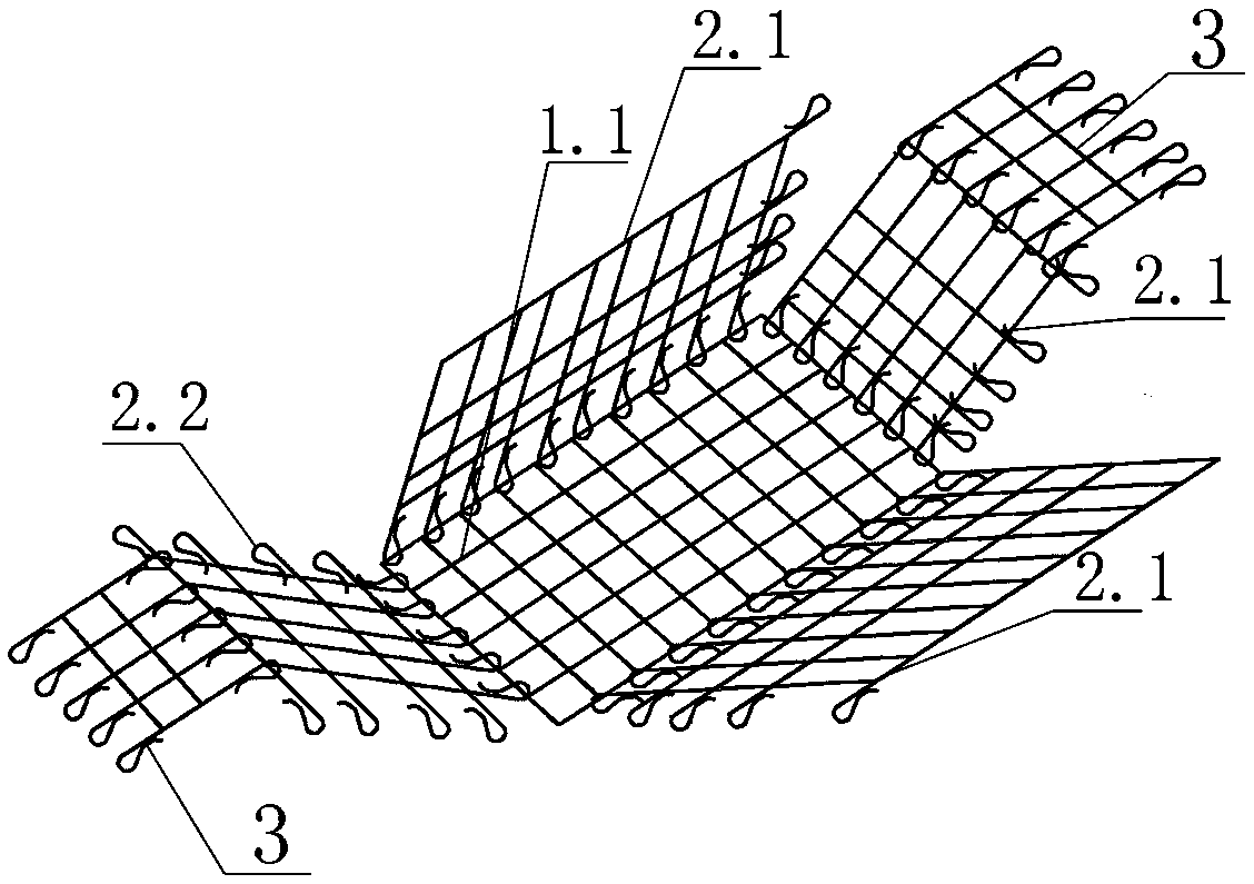
[0038] Such as Figure 1-4 As shown, this kind of precast beam wet joint transverse partition variable space work platform is set at the joint position of two adjacent precast beams for the construction of wet joints; including a floor structure 1, an enclosure structure 2 and the connecting member 3; the floor structure 1 has one, which is horizontally arranged at the bottom of the work platform; the enclosure structure 2 is arranged along the edge of the floor structure 1, and together with the floor structure 1, forms a bottom without cover The enclosure structure 2 is enclosed by at least two first enclosure structure units 2.1 and a second enclosure structure unit 2.2, wherein the two adjacent first enclosure structure units 2.1 Between the first enclosure structure unit 2.1 and the second enclosure structure unit 2.2 are detachable connections; between the bottom edge of the first enclosure structure unit 2.1 and the floor structure 1, the second enclosure structure unit The bottom edge of 2.2 and the floor structure 1 are all hinged connections; there are two connecting members 3, which are arranged on both sides of the top of the enclosure structure 2; the width of the two connecting members 3 is smaller than the width of the construction Wet joint width; among them, the bottom edge of each connecting member 3 is hingedly connected with the top edge of the enclosure structure 2, and the top edge of each connecting member 3 passes through the gap of the embedded steel bars in the wet joint to be constructed, which can be Disassemble and connect to the fixed component above the top surface of the prefabricated beam.
[0039] In this embodiment, the bottom structure 1 is rectangular, and includes a rectangular bottom steel mesh 1.1 welded by steel bars and a bottom plate 1.2 laid on the bottom steel mesh 1.1; wherein the length of the bottom structure 1 is adjusted according to the site Adjustable, based on the principle of lightness, generally less than or equal to 2m (considered according to the width of two adults + instrument operation space); the width of the bottom structure 1 is adjustable without limitation. When it is greater than the width of the wet joint, the vertical steel strip The amplitude is bent to form a variable cross-section operating platform; when the width of the wet joint is less than the width of the wet joint (the construction operation is satisfied), the vertical steel bar does not need to be bent with the amplitude, forming an operating platform with a bottom and no cover.
[0040] Of course, in other embodiments, the floor structure 1 may also be triangular, pentagonal, hexagonal or other polygonal; the first enclosure structure unit 2.1 may be two or three or four, etc., And together with the second enclosure structure unit 2.2 to form a closed box-shaped structure with a bottom and no cover, and the size of the space enclosed between the first enclosure structure unit 2.1 and the second enclosure structure unit 2.2 can be Seam size adjustment.
[0041] In this embodiment, the first enclosure structure unit 2.1 is formed by welding and connecting a group of horizontal steel bars and a group of vertical steel bars, and both the horizontal steel bars and the vertical steel bars are made of Q235 round steel; A hook is provided at the end, and a hook is provided at the lower end of the vertical steel bar.
[0042] In this embodiment, the first enclosure structure unit 2.1 has three, which are connected end to end in turn, and are correspondingly arranged at the three side positions of the bottom steel mesh 1.1; wherein the hooks at the lower end of the vertical steel bars are hooked on the bottom steel bars On the side of the mesh 1.1, and the opening of the lower hook of the vertical steel bar is closed by the tie wire 5; the adjacent first enclosure structure unit 2.1 passes through the first end of the horizontal steel bar in the first enclosure structure unit 2.1 The hook hook is connected to the vertical steel bar at the end of the horizontal steel bar in the other first enclosure structure unit 2.1, and the hook opening at the head end of the horizontal steel bar is tied and closed by the tie wire 5.
[0043] In this embodiment, the shapes of the hooks at the ends of the horizontal steel bars and the vertical steel bars in the first enclosure structure unit 2.1 are in the shape of a bottleneck that shrinks inward near the opening and opens outward at the opening position; and The connections between the horizontal steel bars and the vertical steel bars are all welded connections.
[0044] In this embodiment, the second enclosure structure unit 2.2 is formed by welding and connecting a group of horizontal steel bars and a group of vertical steel bars; wherein, both ends of the horizontal steel bars are provided with hooks, and the lower ends of the vertical steel bars are provided with hooks. Hook.
[0045] In this embodiment, the hook at the head end of the horizontal steel bar in the second enclosure structure unit 2.2 is hooked on the vertical bar at the end of the horizontal bar in the first enclosure structure unit 2.1 on the corresponding side, and the horizontal steel bar The opening of the hook at the head end is closed by the tie wire 5; the hook at the end of the horizontal steel bar in the second enclosure structure unit 2.2 overlaps with the center of the first end hook of the horizontal bar in the first enclosure structure unit 2.1 on the corresponding side, It is connected by a vertical pin 4 inserted in the hook; the hook at the end of the horizontal steel bar in the second enclosure structure unit 2.2 and the first hook opening of the horizontal steel bar in the first enclosure structure unit 2.1 both pass through the wire tie 5 The lashing is closed; the hook at the lower end of the vertical steel bar in the second enclosure structure unit 2.2 is hung on the side of the corresponding side of the bottom steel mesh 1.1, and the opening of the hook at the lower end of the vertical steel bar is tied by the tie wire 5. closure.
[0046] In this embodiment, the shapes of the hooks at the ends of the horizontal steel bars and the vertical steel bars in the second enclosure structure unit 2.2 are in the shape of a bottleneck that shrinks inward near the opening and opens outward at the opening; The connections between the horizontal steel bars and the vertical steel bars are all welded connections.
[0047] In this embodiment, the vertical bolt 4 is a steel bar with an arc-shaped hook at one end; the wire tie 5 is an ordinary wire tie on site.
[0048] In this embodiment, the connecting member 3 is connected by a group of horizontal steel bars and a group of vertical steel bars welded and connected; wherein the upper and lower ends of the vertical steel bars are provided with hooks; Hook the hook at the lower end of the steel bar to the horizontal steel bar on the top of the first enclosure structure unit 2.1 or the second enclosure structure unit 2.2 below it, and the hook opening at the lower end of the vertical steel bar is closed by tying wire 5, and the connecting member 3 The hook at the upper end of the vertical steel bar passes through the gap of the embedded steel bar in the wet joint to be constructed, and is hooked on the fixed member above the top surface of the prefabricated beam, and the hook opening at the upper end of the vertical steel bar is tied by wire tie 5 closure.
[0049] In this embodiment, the shapes of the horizontal steel bars and the hooks at the ends of the vertical steel bars in the connecting member 3 are in the shape of a bottleneck that shrinks inwardly near the opening and opens outwardly at the opening position; and the horizontal steel bars and The connections between the vertical steel bars are all welded connections.
[0050] The manufacturing method of the variable space working platform of the precast beam wet joint transverse partition includes the following steps.
[0051] Step 1: Make the bottom steel mesh 1.1, the first enclosure structure unit 2.1 and the second enclosure structure unit 2.2.
[0052] Step 2: Connect the first enclosure structure unit 2.1 and the second enclosure structure unit 2.2 to the bottom reinforcement mesh 1.1 of the bottom reinforcement mesh 1.1 respectively.
[0053] Step 3: Connect the lower ends of the vertical steel bars in the two connecting members 3 to the horizontal steel bars on the top of the first enclosure structure unit 2.1 or the second enclosure structure unit 2.2 respectively.
[0054] Step 4: Use the hooks on the horizontal steel bars and the hooks on the vertical steel bars to adjust the size of the space and record the hook position. This is beneficial to the initial stage of the assembly platform. The hook position is quickly hooked to avoid cross hooking and normal assembly. Affecting the assembly time, unable to provide a qualified operating platform.
[0055] Step 5: Fold the bottom steel mesh 1.1, the first enclosure structure unit 2.1, the second enclosure structure unit 2.2 and the connecting member 3, and put the folded structure through the gap of the embedded steel bars into the wet joint to be constructed Then, the two connecting members 3 are respectively passed through the steel bar gap above them and protruded from the top surface of the prefabricated beam.
[0056] Step 6: Lay the bottom steel mesh 1.1 flat, adjust the position of the bottom steel mesh 1.1, and use the hook at the upper end of the vertical reinforcement in the connecting member 3 to detachably connect with the fixed member above the top surface of the precast beam.
[0057] Step 7: The operator cooperates with the safety facilities and uses the horizontal steel bars on the first enclosure structure unit 2.1 or the second enclosure structure unit 2.2 as a step to reach the bottom steel mesh 1.1, and then proceed to the first enclosure structure unit 2.1 and The hook connection between the first envelope structure unit 2.1 and the hook connection between the first envelope structure unit 2.1 and the second envelope structure unit 2.2, and finally the horizontal steel bar end in the second envelope structure unit 2.2 Insert the vertical bolt 4 at the position where the hook is connected to the first end hook of the horizontal steel bar in the first enclosure structure unit 2.1 on the corresponding side.
[0058] Step 8: Lay the bottom plate 1.2 on the bottom steel mesh 1.1; at this point, the production of the work platform is completed.
[0059] Step 9: Start the formwork support and transverse diaphragm reinforcement welding operation on the completed work platform. After the completion of the operation, pull out the vertical bolt and use the horizontal reinforcement on the first enclosure structure unit 2.1 or the second enclosure structure unit 2.2 As a ladder step, on the contrary, the hooking of the enclosure structure is dismantled and disassembled into a piece connection, and the parallel embedded steel bars are drawn out of the first enclosure structure unit 2.1, the second enclosure structure unit 2.2 and the connecting member 3, and the entire operation is completed.
[0060] In this embodiment, the bottom steel mesh 1.1 described in step 6 is located in or below the wet joint to be constructed.
[0061] In this embodiment, the fixing member above the top surface of the beam in step 6 is a steel tube member or a section steel member in the beam superstructure.
[0062] The above-mentioned embodiments are not an exhaustive list of specific implementations, and there are other embodiments. The purpose of the above-mentioned embodiments is to illustrate the present invention, not to limit the scope of protection of the present invention. All applications derived from simple changes of the present invention fall into this Within the scope of protection of the invention.

PUM

PropertyMeasurementUnit
Length<= 2.0m

Description & Claims & Application Information

We can also present the details of the Description, Claims and Application information to help users get a comprehensive understanding of the technical details of the patent, such as background art, summary of invention, brief description of drawings, description of embodiments, and other original content. On the other hand, users can also determine the specific scope of protection of the technology through the list of claims; as well as understand the changes in the life cycle of the technology with the presentation of the patent timeline. Login to view more.

Similar technology patents

Workpiece tray rack

Owner:SUZHOU RS TECH

Host computer case convenient to move

InactiveCN106445016Aeasy to move
Owner:芜湖光荣网络科技有限公司

Pesticide spraying device with weed cutting-off function

InactiveCN108633442Aeasy to moveeasy to control
Owner:FUJIAN FUXIN AGRI TECH DEV CO LTD

Classification and recommendation of technical efficacy words

  • easy to move

Backpack medlar-picking machine

InactiveCN101473731Aeasy to movenovel structure
Owner:CHINA AGRI UNIV

Stream media broadcasting method and system

InactiveCN103763637AEasy to transfereasy to move
Owner:CHINA NSTV

Hot-blast stove of biomass energy source

InactiveCN101907354Astructural scienceEasy to move
Owner:SICHUAN HUINONG MACHINERY

Water drainage and gas production simulated experimental device

InactiveCN101806202Aeasy to move
Owner:CHINA UNIV OF PETROLEUM (EAST CHINA)

Hydraulic self-moving steel mould trolley and construction method thereof

ActiveCN103437782AFlexible removal locationeasy to move
Owner:CHINA THREE GORGES CORPORATION +1
Why Eureka
Try Eureka