Plastering device for connecting position of wall body and ceiling

A technology for connecting parts and ceilings, which is applied to buildings and building structures, etc., can solve the problems of increased time cost, easy damage to the coating surface, low efficiency, etc., and achieve the effect of improving work efficiency and increasing time cost.

Inactive Publication Date: 2018-03-30
何茜
0 Cites 0 Cited by

AI-Extracted Technical Summary

Problems solved by technology

[0005] The purpose of the present invention is to provide a plastering device for the connection between the wall and the ceiling, which solves the problem that the existing trowel is used to smear the connection between the wall...

Method used

Because the ceiling is positioned at the top of the builder's head, when smearing, the unstable holding force will cause the trowel to fall to the ground; therefore, the stop bar 16 is set so that when the fingers are unloaded, the position-limiting effect of the s...

Abstract

The invention discloses a plastering device for the connection between a wall and a ceiling, which includes a wiper I and a wiper II, one side of the wiper I is connected to one side of the wiper II, and the wiper I and the wiper II On the opposite surface of II, there are supporting plates and handles connected in sequence; between the wiping plate I and the supporting plate, several telescopic rods are arranged. The axes of the telescopic rods are all perpendicular to the Ⅰ connection, the other end is connected with the support plate. In this way, the wall and the ceiling can be painted at the same time with one wave, which not only avoids damage to the painting surface on the other side when only one side is painted, resulting in repeated repairs in the later stage, which increases time costs; it also improves work efficiency. At the same time, when the wiping board I and the wiping board II are not perpendicular to each other due to collisions or other reasons, adjust the length of the telescopic rod so that the wiping board I and the wiping board II are perpendicular to each other, which is convenient to use the present invention to paint the wall and the ceiling at the same time.

Application Domain

Building constructions

Technology Topic

EngineeringOccurrence time

Image

  • Plastering device for connecting position of wall body and ceiling
  • Plastering device for connecting position of wall body and ceiling
  • Plastering device for connecting position of wall body and ceiling

Examples

  • Experimental program(1)

Example Embodiment

[0039] Example 1
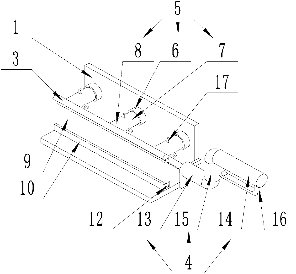
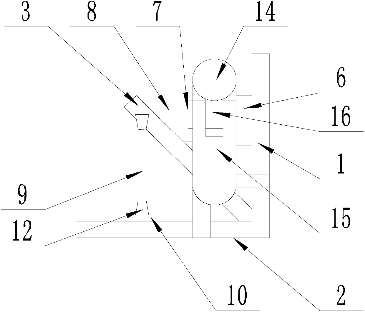
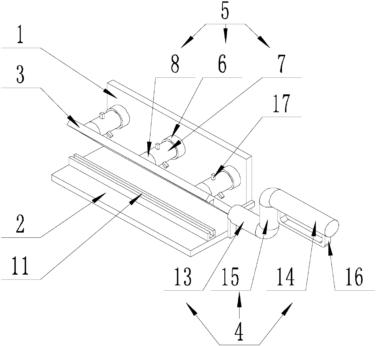
[0040] Such as Figure 1-Figure 5 As shown, the plastering device for the connecting part of the wall and the ceiling of the present invention includes a wiper board I1 and a wiper board II2. One side of the wiper board I1 is connected to one side of the wiper board II2, and the wiper board I1 and the wiper board II2 are connected. The boards II2 are perpendicular to each other. On the opposite surfaces of the wipe board I1 and the wipe board II2, there are provided a support board 3 and a handle 4 connected in sequence. One side of the support board 3 is connected with the wipe board I1 and the wipe board II2. The parts are connected, and the support plate 3 is parallel to the connecting edge between the wiper board I1 and the wiper board Ⅱ2, and the right angle formed between the wiper board I1 and the wiper board II2 is equally divided;
[0041] One end of the handle 4 is connected to one end of the support plate 3, and the other end of the handle 4 extends in a direction away from the support plate 3;
[0042] A number of telescopic rods 5 are arranged between the wiper board I1 and the support board 3, the axes of the telescopic rods 5 are all perpendicular to the wiper board I1, one end is connected to the wiper board I1, and the other end is connected to the support board 3. , And the telescopic rod 5 is arranged between the wiper board I1 and the support board 3 at even intervals along the connecting edge line between the wiper board I1 and the wiper board II2.
[0043] When painting the connecting part between the wall and the ceiling, hold the handle 4 so that the wiping board I1 is in contact with the wall, and the wiping board Ⅱ2 is in contact with the ceiling, so that the wall and ceiling are painted. This way, the wall and the ceiling can be painted at the same time with one wave, which not only avoids damaging the painted surface on the other side when applying one side alone, causing repeated repairs in the later period and increasing the time cost, but also improves the work efficiency.
[0044] At the same time, when the wiper board I1 and the wiper board II2 are not perpendicular to each other due to collisions, etc., adjust the length of the telescopic rod 5 so that the wiper board I1 and the wiper board II2 are perpendicular to each other, so that the present invention and the wall and the ceiling The angles are consistent, which facilitates the simultaneous application of the wall and the ceiling using the invention. For example, when the angle between the wiper board I1 and the wiper board II2 is an acute angle, the length of the telescopic rod 5 is increased so that the wiper board I1 moves away from the support board 3, and then the wiper board I1 and the wiper board Ⅱ The plate II2 is perpendicular to each other; when the angle between the wiper board I1 and the wiper board Ⅱ2 is an obtuse angle, the length of the telescopic rod 5 is shortened so that the wiper board I1 is pulled toward the support board 3, and then the wiper board I1 and Wiping boards II 2 are perpendicular to each other.
[0045] Further, the telescopic rod 5 includes a threaded barrel 6, a screw 7 and a fixing block 8 which are connected in sequence and coaxially. The bottom of the threaded barrel 6 is connected to the wiper plate I1, and one end of the screw 7 is inserted into the threaded barrel 6. The other end of the screw 7 is rotatably connected with the fixed block 8. The end of the fixed block 8 far away from the screw 7 is connected with the support plate 3, and the screw 7 can rotate around its own axis. And the fixed block 8 does not rotate.
[0046] When shortening or extending the telescopic rod 5, the screw 7 can be rotated.
[0047] Preferably, the wiper board I1 and the wiper board II2 are formed by bending a steel plate, the portion of the steel plate on the bent side is the wiper board I1, and the portion on the other side of the bend is the wiper board II2; When the smearing angle is obtuse or acute, adjust the length of the telescopic rod 5 to enlarge the angle between the wiper Ⅰ1 and the wiper Ⅱ2 or reduce the included angle between the wiper Ⅰ1 and the wiper Ⅱ2; compared to the direct welding connection For wiper Ⅰ1 and wiper Ⅱ2, the adjustable angle between wiper Ⅰ1 and wiper Ⅱ2 formed by bending a steel plate is larger and the service life is longer.
[0048] A rotating rod 17 is provided on the side wall of the screw 7 close to the fixed block 8. The axis of the rotating rod 17 is perpendicular to the axis of the screw 7.
[0049] There are three rotating rods 17 and they are symmetrically arranged on the side wall of the screw 7 along the axis of the screw 7.
[0050] The setting of the rotating rod 17 makes the rotating screw 7 more labor-saving.
[0051] Further, a limit plate 9 is slidably arranged between the wipe board II2 and the support plate 3, and the limit board 9 is parallel to the connecting edge line between the wipe board I1 and the wipe board II2;
[0052] A mounting block 10 is provided on the end of the wiper plate II2 close to the support plate 3, and an end of the mounting block 10 far away from the wiper plate II2 and the end of the support plate 3 near the wiper plate II2 are both provided with a mounting groove 11, the mounting groove The axes of 11 are parallel to the connecting edge line between the wiper board I1 and the wiper board II2, and the opening size of the mounting groove 11 is smaller than the groove bottom size;
[0053] Both ends of the limit plate 9 are provided with connecting blocks 12, the cross-sectional size of the connecting block 12 and the cross-sectional size of the mounting groove 11 are the same, the connecting blocks 12 are respectively fitted with a mounting groove 11, and can be installed along the The axis of the groove 11 moves.
[0054] The installation groove 11 is a dovetail groove.
[0055] The setting of the limit plate 9 not only fixes the angle between the support plate 3 and the wiper Ⅱ2, but also facilitates the support for the wiper Ⅱ2, which is beneficial to control the wiper Ⅱ2 when applying wall dust.
[0056] Further, the handle 4 includes a fixed rod 13 parallel to each other, a holding rod 14, and a connecting rod 15 arranged between the fixed rod 13 and the holding rod 14. One end of the fixed rod 13 is connected to the support plate 3 to fix The other end of the rod 13 is connected to one end of the holding rod 14 through the connecting rod 15, and the axis of the connecting rod 15 is perpendicular to the axis of the fixing rod 13.
[0057] Further, a U-shaped stop rod 16 is provided on the side wall of the holding rod 14. The ends of the stop rod 16 are connected to the side wall of the holding rod 14, and the stop rod 16 and the holding rod 14 are enclosed The axis of the hole is perpendicular to the axis of the holding rod 14.
[0058] Because the ceiling is located above the head of the construction worker, the unstable holding force will cause the trowel to fall to the ground during painting; therefore, the stop lever 16 is set to prevent the stop lever 16 from being held when the fingers are loosened. The trowel will fall off directly from the fingers, thus reducing the probability of the trowel falling off the hand when the holding is unstable.

PUM

no PUM

Description & Claims & Application Information

We can also present the details of the Description, Claims and Application information to help users get a comprehensive understanding of the technical details of the patent, such as background art, summary of invention, brief description of drawings, description of embodiments, and other original content. On the other hand, users can also determine the specific scope of protection of the technology through the list of claims; as well as understand the changes in the life cycle of the technology with the presentation of the patent timeline. Login to view more.

Similar technology patents

Large size mounting RFID upside-down mounting pasting method and apparatus thereof

InactiveCN102324393AImprove work efficiencysave sample time
Owner:广东宝丽华服装有限公司

Device for removing low-melting-point alloy from inner cavity of blade

ActiveCN106761953Ashort removal timeImprove work efficiency
Owner:CHINA HANGFA SOUTH IND CO LTD

Classification and recommendation of technical efficacy words

  • Improve work efficiency

Cooperation service platform facing different source data

InactiveCN101174957AImprove management level and qualityImprove work efficiency
Owner:NANJING UNIV OF FINANCE & ECONOMICS

Screw drilling tool, vertical drilling tool testing method and well inclination simulation testing equipment

InactiveCN111594144AReduced height requirementsImprove work efficiency
Owner:DEZHOU UNITED GASOLINEEUM MACHINERY

Method for intelligent automatic identification of transmission circuit parts

Owner:INFORMATION COMM COMPANY STATE GRID SHANDONG ELECTRIC POWER +2

Keyboard spill-proofing mechanism

ActiveUS7030330B2minimize manufacturing costimprove work efficiency
Owner:LITE ON SINGAPORE PTE LTD
Why Eureka
Try Eureka