
Yaw speed reducer output device

A technology of output device and reducer, applied in transmission parts, mechanical equipment, belts/chains/gears, etc., can solve the problems of uneven bearing force, reduce gear strength, tooth surface meshing eccentric load, etc. The effect of strength, uniform load on tooth surface and simple structure

Inactive Publication Date: 2018-03-30
TAIYUAN HEAVY IND
View PDF5 Cites 2 Cited by
  • Summary
  • Abstract
  • Description
  • Claims
  • Application Information

AI Technical Summary

Problems solved by technology

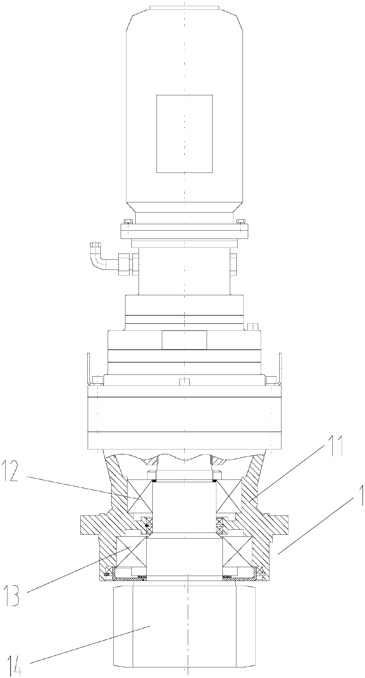
like figure 1 As shown, the output structure 1 of the yaw reducer includes a housing 11, a first upper bearing 12 and a second upper bearing 13 installed on the housing 11, and a gear 14 of the output shaft. The output of the existing yaw reducer The shaft adopts a cantilever structure. The main problem of this structure is that the two bearings are unevenly stressed. The bearing of the gear 14 near the output shaft is heavily stressed and easily damaged. In order to meet the requirements of use, it is difficult to select the bearing type during design. Seriously, the meshing and partial load of the tooth surface is serious, which reduces the strength of the gear

Method used


Image

  • Yaw speed reducer output device
  • Yaw speed reducer output device

Examples


Embodiment Construction

[0017] In order to make the purpose, technical solutions and advantages of the embodiments of the present invention clearer, the technical solutions of the present invention will be clearly and completely described below in conjunction with the embodiments of the present invention and corresponding drawings. Apparently, the described embodiments are only some of the embodiments of the present invention, but not all of them. Based on the embodiments of the present invention, all other embodiments obtained by persons of ordinary skill in the art without making creative efforts belong to the protection scope of the present invention.

[0018] The terms "first", "second", etc., if present, in the description and claims and the above drawings are used to distinguish similar parts and not necessarily to describe a specific order or sequence. It is to be understood that the data so used are interchangeable under appropriate circumstances such that the embodiments of the application d...


PUM


Abstract

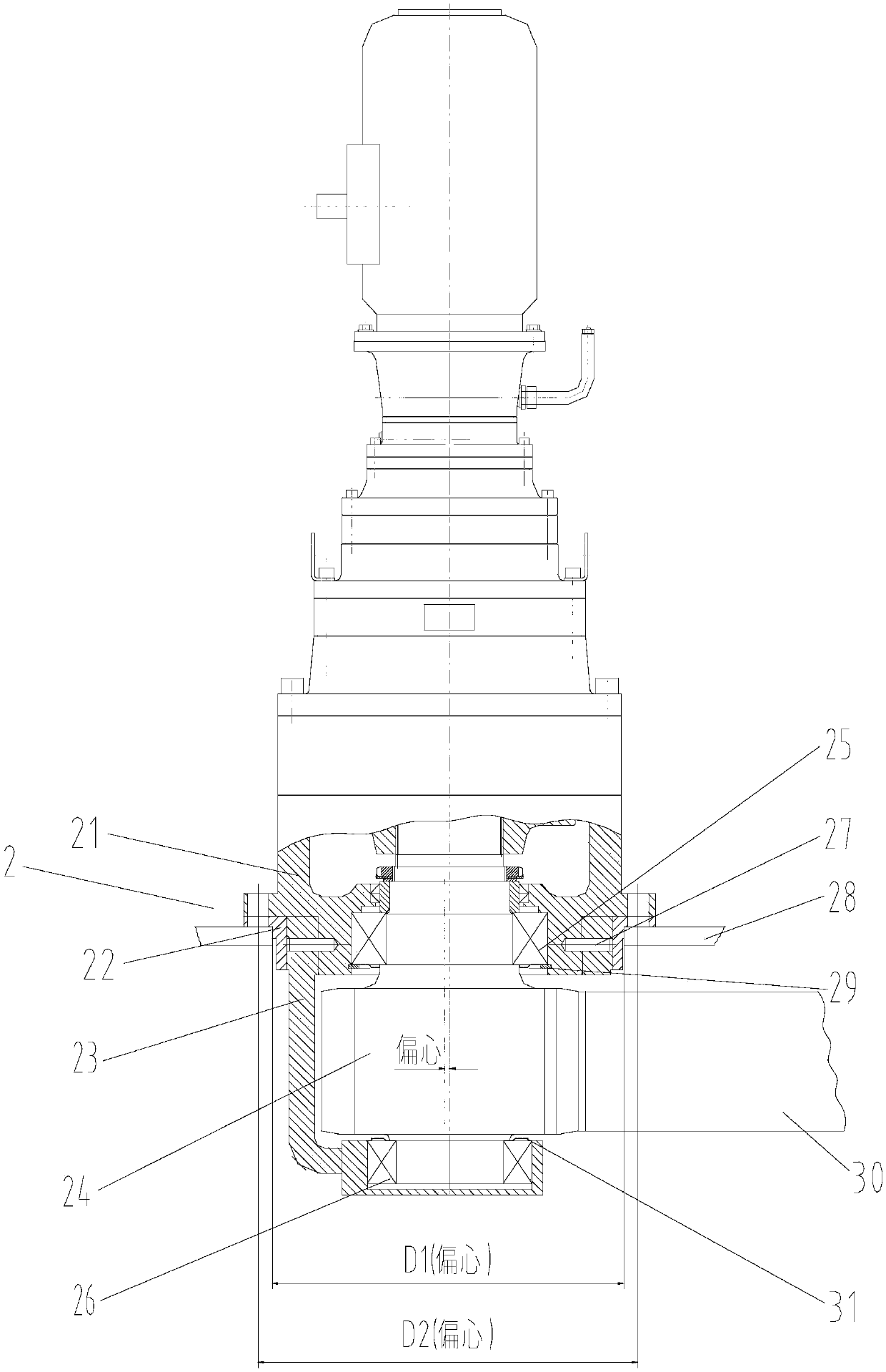
The invention provides a yaw speed reducer output device which comprises a first shell, an upper bearing installed on the first body, an output shaft gear, a half-surrounded second shell in matched connection with the first shell through a cylindrical pin, a lower bearing installed on the second shell, an eccentric ring on the outer face of the second shell, and upper and down dustproof rings forsealing lubricating grease of the upper and lower bearings. In the yaw speed reducer output device, two-end supporting is adopted for the output shaft gear, the tooth face load is uniform when an output small gear is engaged with a rotary large gear ring, and the gear strength is improved. In order to solve the problem of stress uniform load when multiple yaw speed reducers are engaged with the rotary large gear ring, the tooth side gaps of pairs of engaged teeth are ensured same, the eccentric ring is adopted for each yaw speed reducer to adjust the gear engagement center distance, namely theside gap, it is ensured that the output shaft gear is correctly engaged with the large gear ring, and the problem that the gap position of the half-surrounded second shell cannot be changed is solved. On the other hand, the second shell plays a protection role in the output small gear.

Description

technical field [0001] The invention relates to the technical field of wind power generation transmission, in particular to a yaw reducer. Background technique [0002] At present, with the rapid rise of offshore wind power generation, large-megawatt-level wind power generation units above 3MW have developed rapidly. The yaw reducer is one of the essential devices in the wind turbine control system. The main function of the yaw reducer is to drive the nacelle to rotate and track the change of the wind direction. After the yaw process is over, it acts as a part of the brake nacelle. , which plays an extremely important role in the amount of power generated by wind turbines. [0003] The yaw reducer is located at the bottom of the nacelle, a large rotary ring gear is installed on the tower side of the wind turbine, multiple yaw reducers are assembled on the nacelle side, and the machine base installed on the nacelle is used to support and fix multiple yaw reducer. Among the...

Claims


Application Information

Patent Timeline
Patent Type & Authority Applications(China)
IPC IPC(8): F16H57/021F16H57/023F16H57/025F16H57/029F16H57/12
Inventor 陈秀花赵恒吴亚军曹斌
Owner TAIYUAN HEAVY IND
Learn More